
Ducati Diavel Service Manual: Horn not working
Fault codes
Dds: horn diagnosis -> short circuit to ground (s.C. Gnd).
Dashboard: the error "claxon" (horn) is shown on the service display. The eobd warning light activates.
Wiring diagram
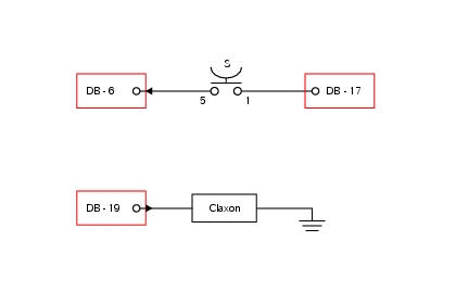
Db dashboard connection, s horn button. 5 Blue/white - b/w, 1 red/blue - r/b, db 19 purple/black - v/bk.
Location of connections and components
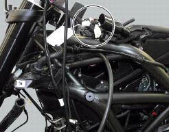
Location of left hand handlebar switchgear set connection.
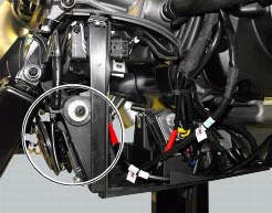
Location of horn with relative connection.
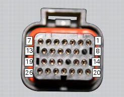
Pin numbering for wiring harness side dashboard connector.
Note
Check integrity of electric circuit - short-circuit to vdc = with dashboard on, using a voltmeter, a voltage is measured between the wire tested and ground.
Check integrity of electric circuit - short-circuit to ground = with the battery cables disconnected, using an ohmmeter, continuity is detected between the wire tested and ground.
Check integrity of electric circuit - open circuit = with the battery cables disconnected, using an ohmmeter, no continuity is detected between the two ends of the wire tested.
 Low beam lights not working
Location of connections and components
(A) injection relay; (b) etv relay (throttle valve operating engine); (c)
radiator fan relay; (d) hands free relay.
Fuses located at the rear left of ...
 Turn indicators not working
Fault codes
Dds: no fault code displayed.
Dashboard: no fault code displayed.
Wiring diagram
Db dashboard connection, bbs bbs unit connection, s turn indicator button, f1
front left turn i ...
Other materials:
Default function (resetting ducati default parameters)
This function resets the parameters set by ducati for each
riding style.
To access the function it is necessary to view the "setting" menu page 48, using
button (1, fig. 14) ?"
" or (2, fig. 14) ?" " select the "riding mode"
function and press the
r ...
Refitting the hands free
Reassembly is a reversal of the removal procedure: in particular apply
prescribed threadlocker to screws (2) and tighten
them to a torque of 20 nm +/- 10% (sect. 3 - 3, Frame torque settings).
If the hands free button has been previously removed, when refitting it insert
the spring (6) on pi ...
Abs diagnosis
Note
The on-screen icons used during this procedure are explained in a table at
the end of this section.
If the abs system is not working correctly, system diagnosis is possible
through the dds diagnosis instrument.
Turn on the dds diagnosis instrument (1) referring to the paragraph "tester ...