
Ducati Diavel Service Manual: Information about the model
Identification data
Diavel identification data
Each ducati motorcycle has two identification numbers -the frame number and the engine number- and an ec nameplate (a) (not present on the us version).
Note
Please quote these numbers, which identify the motorcycle model, when ordering spare parts.
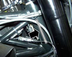
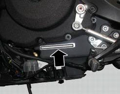
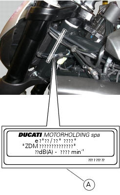
Data stamped on the frame
Europe version
- Manufacturer: ducati motor holding
- Type - same for all diavel / diavel carbon models
- Variant
- Version: aa = diavel / diavel carbon
Ab = diavel abs / diavel carbon abs
- Year of manufacture:
(A=2010)
(B=2011)
- Manufacturing facility
- Progressive serial no.
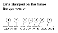
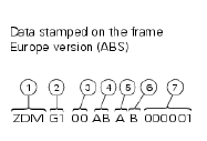
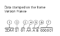
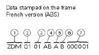
Data stamped on the frame
Us version
- Manufacturer: ducati motor holding
- Motorcycle type
- Variant - numeric or x (check digit)
- Variant - numeric or x (check digit)
- Manufacturing facility
- Progressive serial no.
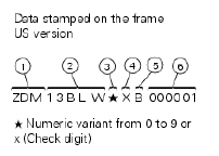
Data stamped on engine
Europe version
- Manufacturer: ducati motor holding
- Engine type
- Progressive production no.
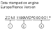
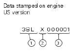
Data stamped on engine
Us version
- Engine type
- Model year (b=2011)
- Progressive production no.
 General maintenance indications
Useful tips
Ducati recommends that you follow the instructions below in order to prevent
problems and obtain the best end result:
When diagnosing faults, primary consideration should always be ...
 Technical data
...
Other materials:
Refitting the front footrests
Note
The assembly of the front footrests is described only for the right one
(2) but it is the same also for the left one.
Place the spring (4) bringing the end (a) onto the footrest (2).
Place the footrest (2) in the correct position, by inserting the end (c) of the
spring (4) in the hole ...
Routing of wiring on frame
The routing of the wiring has been optimised to ensure the minimum
obstruction.
Each section is designed to prevent interference with parts that might damage
wires or cause operating failures when
riding. The plates on the following pages show the origins ("0" points) for
correct re-routin ...
Removal of the shock absorber support
Remove the rear brake master cylinder (sect. 7 - 4, Removing of the rear
brake control).
Remove the rear shock absorber (see removal of the rear shock absorber of this
section).
Loosen the screws (2) and (7) and their nuts (35).
Remove the side stand (sect. 7 - 16, Removing of the ...