
Ducati Diavel Service Manual: Injectors
Introduction
The injectors used on the diavel are top feed units, meaning that fuel is fed into the top of the injector itself. The injectors contain a winding which raises a needle when electrically energised. This opens the atomiser nozzle, through which pressurised fuel is dispensed, generating the spray that mixes with the air aspirated by the engine. To ensure that The spray consists of perfectly atomised fuel, the atomiser nozzle has twelve holes. Each cylinder has an injector, located underneath the respective throttle valve. The injector aperture time is determined by the engine control unit to ensure that the correct quantity of fuel is injected (carburation).
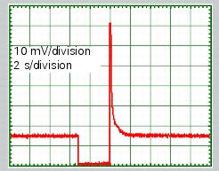
The graph shows the quantitative variation in the signal sent to the injector by the ecu in relation to time. The ecu commands injector aperture by creating a connection to ground at one of the terminals of the injector's electric winding.
The other terminal receives 12v power supply voltage.
Component assembling position
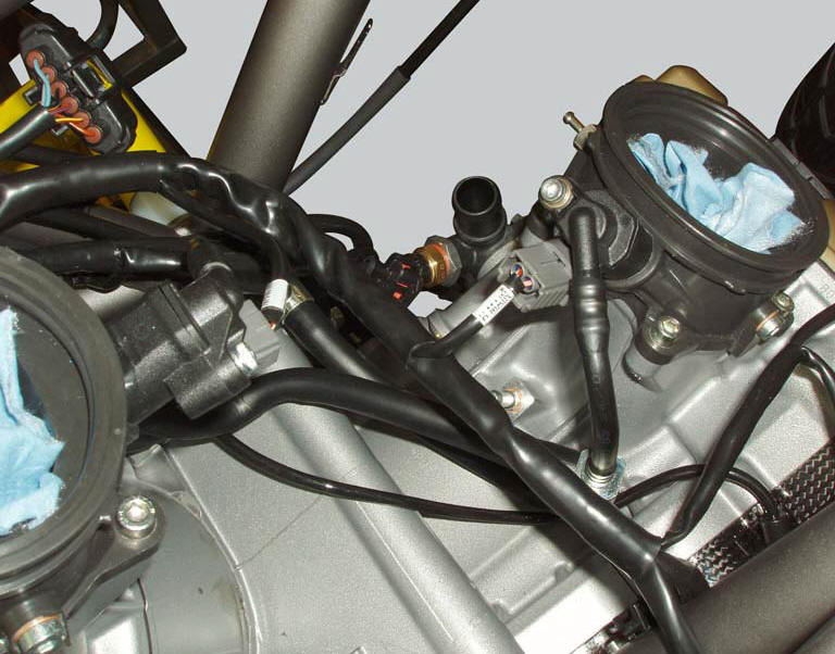
The injectors are located on the intake ducts, underneath the throttle valve. The respective electrical connection is integrated into the injector body.
Connection wiring diagram
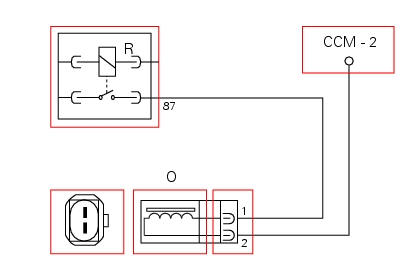
O horizontal cylinder injector, r injection relay. Ccm engine control connection, 1 power connection (12v) via injection relay (brown/white - bn/w), 2 connection to control unit (pink/yellow - p/y).

V vertical cylinder injector, r injection relay. Ccm engine control connection, 1 power connection (12v) via injection relay (brown/white - bn/w), 2 connection to control unit (green/yellow - g/y).
In the event of fault
The cylinder associated with the faulty injector does not function.
Fault codes generated and possible correlated faults
Fault codes generated by engine control unit and displayed by dds (vertical injector diagnosis (inj. 2), Horizontal injector diagnosis (inj. 1)):
- Injector 1 (cylinder 1 - horizontal) and/or injector 2 (cylinder 2 - vertical), open circuit: check integrity of electric circuit and electrical connections.
- Injector 1 (cylinder 1 - horizontal) and/or injector 2 (cylinder 2 - vertical), short circuit to vdc: check integrity of electric circuit and electrical connections.
- Injector 1 (cylinder 1 - horizontal) and/or injector 2 (cylinder 2 - vertical), short circuit to ground: check integrity of electric circuit and electrical connections.
Check integrity of electric circuit - short-circuit to vdc = with dashboard on, using a voltmeter, a voltage is measured between the wire tested and ground.
Check integrity of electric circuit - short-circuit to ground = with the battery cables disconnected, using an ohmmeter, continuity is detected between the wire tested and ground.
Check integrity of electric circuit - open circuit = with the battery cables disconnected, using an ohmmeter, no continuity is detected between the two ends of the wire tested.
The dashboard service display shows the error "injector" and the eobd warning light activates.
Possible correlated faults:
- If the engine does not start and the injectors are not supplied with 12 v, check the injection relay operation (see paragraph "injection relay") of this section.
- If the engine is running on once cylinder only and one of the injectors does not open, try swapping the injectors. If the fault (no injector opening) follows the injector, the injector itself is faulty. If the fault does not follow the injector, the relevant control circuit is faulty.
- If the engine runs irregularly, check the pressure and flow rate in the fuel circuit (see paragraph "fuel system circuit" of this section) and check that the injectors atomise the fuel correctly.
The injectors may be actuated from the dds to check that they function correctly.
If none of the aforementioned tests identify the problem and the injectors are in proper working order, replace the engine control unit.
Component replacement methods
The injectors replacement do not foresee particular measures, proceed as described in sect. 8 - 6, Removal of the fuel injectors. With the fuel system pressurised, check that there are no fuel leaks from the connector. After replacement of one or both of the injectors, reset the self-adaptive parameters relative to carburation with the dds.
 Ignition coils
Introduction
The engine control system of the diavel includes two ignition coils: one for
the horizontal cylinder and one for the vertical
cylinder. These coils are installed directly in the spark ...
 Throttle valve operation engine
Introduction
The electric motor actuating the throttle valve for the vertical cylinder is
mounted on the throttle body of the diavel, while
a link rod connects the vertical cylinder throttle valve ...
Other materials:
Checking and adjusting the valve clearances
Note
For clarity, the figures show the engine removed from the frame.
Move the piston of the cylinder being checked to tdc of the power stroke: in
this condition, all the valves are closed and
the timing shafts come in neutral position and, therefore, free to rotate; check
to the valve cl ...
Pre-ride checks
Warning
failure to carry out these checks before riding, may
lead to motorcycle damage and injury to rider and passenger.
Before riding, perform a thorough check-up on your bike as
follows:
Fuel level in the tank
Check the fuel level in the tank. Fill tank if needed (page 140).
Engine oil le ...
Symbols - abbreviations - references
To allow quick and easy consultation, this manual uses graphic symbols to
highlight situations in which maximum care is
required, as well as practical advice or information. Pay attention to the
meaning of the symbols since they serve to avoid
repeating technical concepts or safety warnings th ...