
Ducati Diavel Service Manual: Inspection of the gear selector drum
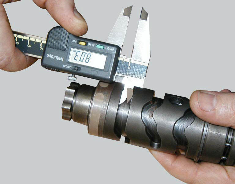
Use a gauge to measure the clearance between fork pin and the slot on the selector drum.
If the service limit is exceeded, determine which part must be replaced by comparing these dimensions with those of new components (sect. 3 - 1.1, Gearbox).
Also check the wear on the drum support pins; these must not show any signs of scoring, burrs, or deformation.
Turn the drum in the crankcase to establish the extent of radial play. If play is excessive, change whichever part is most worn.
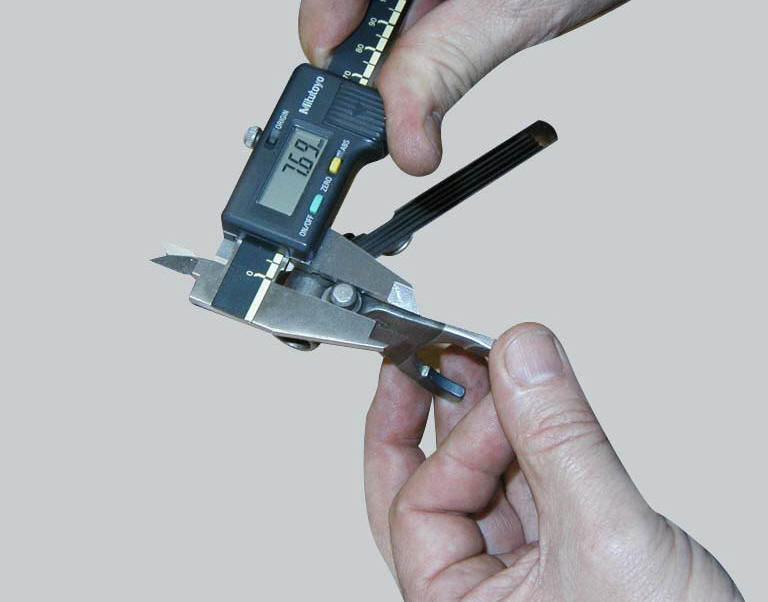
 Inspection of the gear selector forks
Visually inspect the gear selector forks. Bent forks must be renewed as they
may lead to difficulties in gear changing or
may suddenly disengage when under load.
Use a feeler gauge to check the ...
 Reassembly of the gearbox shafts
Figure 1 shows all the parts to be reassembled on the gearbox primary shaft
(2), with the calculated end shims (1) and
(11) (sec. 9 - 9.2, Reassembly of the crankcase halves).
Figure 2 shows a ...
Other materials:
Traction control (dtc) deactivated
The activation of this (amber yellow) "warning" indicates
that dtc (ducati traction control) has been turned off.
Note
In this case, ducati recommends being very careful
when riding as the vehicle behaviour will be different in
comparison to when operating with the traction control
...
Riding safety
The points given below are applicable for every day
motorcycle use and shoud be carefully observed for safe and
effective vehicle operation.
A motorcycle does not provide the impact protection of an
automobile, so defensive riding in addition to wearing
protective apparel is extremely importa ...
Checking and adjusting the valve clearances
Note
For clarity, the figures show the engine removed from the frame.
Move the piston of the cylinder being checked to tdc of the power stroke: in
this condition, all the valves are closed and
the timing shafts come in neutral position and, therefore, free to rotate; check
to the valve cl ...