
Ducati Diavel Owners Manual: Instrument panel diagnosis
This function identifies any abnormal vehicle behaviours.
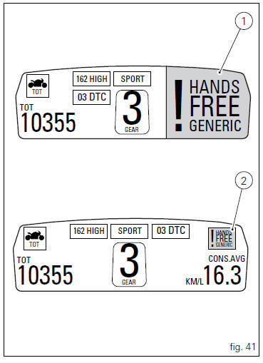
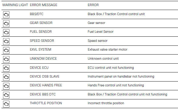
The instrument panel activates any abnormal vehicle behaviours in real time (errors).
At key-on (at the end of the check) one or more "errors" are displayed in red (only if they are active).
When an "error" is triggered, the indication (red) remains well visible for 10 seconds (1, fig. 41) Then becomes smaller (2, fig. 41).
If there are multiple errors, they will scroll automatically every 3 seconds. The "engine/vehicle diagnosis - eobd" light on instrument panel located on handlebar (7, fig. 4) Always turns on when one or more errors are activated.
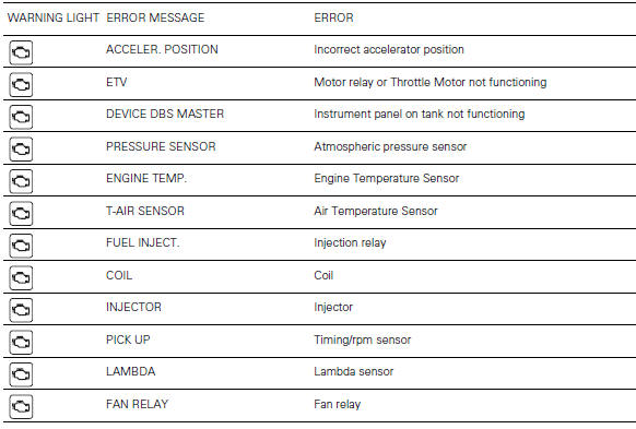
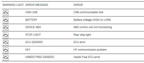
The table below shows the errors that can be displayed.
 Warning
When one or more errors are displayed, always contact a ducati dealer or authorised service centre.
 Steering release error - steering still locked
The activation of this (amber yellow) "warning" indicates
that the hands free system was not able to extract the
steering lock.
Warning
In this case, ducati recommends turning the vehic ...
 Setting menu
This menu is used to enable/disable and set some
motorcycle functions.
To access the "setting menu" press the button (2, fig. 14)
? for 3 seconds.
Note
When within this menu no ...
Other materials:
Indicator air - air temperature
This function shows the external temperature.
Display limits: -39C - +124C
In the event of a sensor fault (-40C, +125C or disconnected), a string of
dashes "- - -" (not flashing) is displayed and
the "vehicle/engine diagnosis - eobd" light comes on.
Note
When the vehicle is stopped, the ...
Front brake control
Front brake master cylinder
Brake lever
Special screw
Sealing washer
Screw
Phonic wheel
Brake disc
Pin
Left brake calliper
Boot
Bleed valve
Spare stand
Control unit - front callipers pipe
Microswitch
Oil duct union
Screw
Hose clip
Right brake calliper
Speci ...
Coolant expansion tank
Plug
Screw
Fuel filler flange
Clip nut
Clamp
Hose clip
Valve/tank hose
Clamp
Screw
Spacer
Rubber mounting
Expansion reservoir
Filler cap
Hose clip
Support
Screw
Washer
Screw
Hose clip
Breather hose
Clamp
Pump/radiator sleeve
Radiator/radiator sleeve ...