
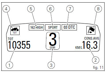
Ducati Diavel Owners Manual: Instrument panel on tank
- Menu 1 (tot, trip1, trip2, trip fuel).
- Menu 2 (cons.Avg., Cons., Speed avg, air and trip time) if active.
- Gear / neutral indication.
- Icon referred to the function below from menu 1.
- Indication of engine setting for the currently set riding style.
- Currently set riding style (riding mode).
- Indication of the intervention level of the dtc (traction control) for the currently set riding style.
- Icon referred to the function below from menu 2.
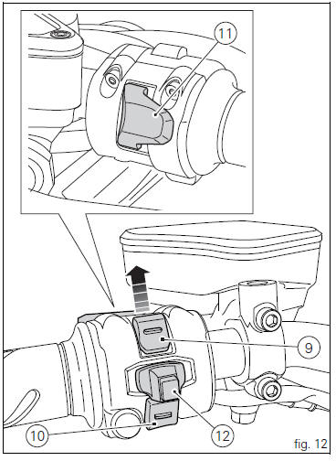
- Control button (fig. 12).
Button used to display and set instrument panel parameters
with the position  .
.
- Control switch (fig. 12).
Button used to display and set instrument panel parameters
with the position  .
.
- High-beam flasher button flash (fig. 12).
The high-beam flash button may also be used to for lap functions.
- Reset button (fig. 12).
The turn indicators off button may also be used for the reset/confirm function on the instrument panel and for activating the "riding style".
 Display background colour (automatic adjustment)
Instrument panel background colour is set automatically
according to exterior lighting conditions.
When sensor detects "poor lighting" (night), it switches to
black background mode; vic ...
 Tft - parameter setting/display
Warning
Any adjustments to the instrument panel must only be
carried out when the motorcycle is stationary. Never operate
the instrument panel controls while riding the motorcycle.
At the end of ...
Other materials:
Horn not working
Fault codes
Dds: horn diagnosis -> short circuit to ground (s.C. Gnd).
Dashboard: the error "claxon" (horn) is shown on the service display. The eobd
warning light activates.
Wiring diagram
Db dashboard connection, s horn button. 5 Blue/white - b/w, 1 red/blue - r/b,
db 19 purple/bl ...
Water pump
Screw
Washer
Circlip
Water pump outlet union
Bearing
bearing
Spacer
Aluminium gasket
Mechanical seal
Water pump impeller
Bush
Water pump cover assembly
Screw
Plug
Sealing washer
Generator cover
Special washer
Fuel filler flange
Spare parts catalogue
Diave ...
Check the engine oil pressure
Note
The on-screen icons used during this procedure are explained in a table at
the end of this section.
To measure the pressure of the lubrication circuit, use the engine oil pressure
test point (19) as described below.
Disconnect the wiring connector (f) of pressure switch (1) and rem ...