
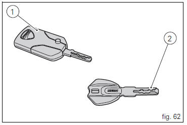
Ducati Diavel Owners Manual: Keys (fig. 62)
The owner receives a set of keys comprising:
- 1 Active key (1, fig. 62)
- 1 Passive key (2, fig. 62)
It contains the code used by the "hands free" system for the key-on, in different modes.
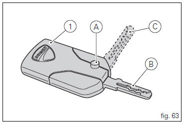
The active key (1, fig. 63) Is the one that is normally used: press button (a, fig. 63) To fully open the metal part, i.E.
Position (b, fig. 63). Holding depressed button (a, fig. 63) You can move the metal part and set it to the middle position (c, fig. 63); Once in place, release button to lock.
The metal part returns inside the grip by pushing it in.
The key contains a battery that must be replaced when the low key battery "warning" is displayed as soon as the instrument panel is turned on (fig. 64).
 Note
Note
In this case, replace the battery as soon as possible (page 88).
When the charge level goes below a certain limit, the key can only work in passive mode, like the passive key: in this case, the instrument panel will not display any message.
 Warning
Do not ride with the key (1 or 2, fig. 62) Inserted in the lock of the tank cap or in the seat lock as it could come out and represent a potential danger. Furthermore, if bumped, the key mechanism and the integrated circuit could be damaged.
Also riding in poor weather conditions with the key inserted could cause damage to its integrated circuit.
Do not leave the key on the motorcycle when washing it as it could be damaged, not being watertight.
 The immobilizer system
For additional antitheft protection, the motorcycle is
equipped with an immobilizer, an electronic system that
locks the engine automatically whenever the ignition switch
is turned off.
The grip ...
 Replacing the battery in the active key
Only use 3 volt cr 2032 lithium ion batteries.
Note
The keys do not need to be reprogrammed after
replacing the battery.
Remove the metal part of the battery.
Use a large sized coin to pry ope ...
Other materials:
Refitting the swingarm
Apply the recommended threadlocker to the screws (7).
Install the lower chain guard (15) on the swingarm (8), fastening it with the
screws (7): tighten the screws (7) to a torque
of 4 nm +/- 10% (sect. 3 - 3, Frame torque settings).
Locate the swingarm (8) on the frame.
Lubricate with ...
Flywheel - alternator
Screw
Alternator stator
Plug
Sealing ring
O-ring
Cover
Screw
Aluminium gasket
Screw
Bracket
Locating bush
Screw
generator cover
Flange
Flanged nut
Plane washer
Flywheel
Washer
Inner ring
Needle roller bearing
Electric starter driven gear
Starter clutc ...
Refitting the throttle twistgrip
Lubricate the ends of the throttle grip cables (10) and the twistgrip race
with the recommended grease.
The closing cable (10) features a writing on the yellow tube, whereas the
opening one (10) features such writing on the
white tube.
To refit the throttle control components, proceed i ...