
Ducati Diavel Service Manual: Lap activation/deactivation function (lap time)
This function activates and deactivates the lap function (lap time).
To access the function it is necessary to view the ""setting" menu", using buttons (1) "s" or (2) "t" select the "lap" function and press the reset button (3) to enter the following page.
Function state is highlighted on the display (on in green or off in yellow); use button (1) "s" or (2) "t" to shift the arrow to the left onto the new setting and confirm by pressing the reset button (3).
To exit the setting function, press the reset button (3) when "exit" is highlighted.
Storing the "off" condition disables the lap function.
Storing the "on" condition enables the lap function (see "lap registration" paragraph).
Note
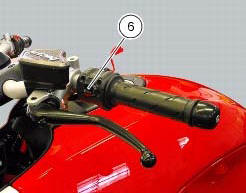
While the "lap" function is active, the flash headlight button (6) both flashes the high beam headlight and starts/stops the lap timer.
 Digital rpm indication function
This function displays the number of rpms for improved accuracy when setting
idle rpm.
To access the function it is necessary to view the ""setting" menu", using
buttons (1) "s" or (2) "t" select ...
 Lap registration function
This function describes the "lap" time registration.
If the function is activated (see "lap activation/deactivation description), the
lap time can be registered as follows:
pressing the flash he ...
Other materials:
Radiator fan relay
Introduction
The radiator fans are powered via a specific relay, which is enabled by the
engine control unit.
Component assembling position
A injection relay; b etv relay (throttle valve actuator motor), c radiator
fan relay, d engine control unit.
Location of right hand fan connecti ...
Checking protection and safety device components
Checking the side stand switch
Remove the switch (1) from the side stand undoing screw (2) and disconnect
the main wiring connector from the switch
(see paragraph "routing of wiring on frame", sect. 6 - 1).
Use an analogue or digital multimeter (sect. 6 - 11, Using a multimeter to check
the ...
Removal of the exhaust system
Remove the silencer, as described in the paragraph "removing the silencer" of
this section.
Loosen the screws (28) and remove the exhaust by-pass valve cover (27).
Turn the exhaust valve pulley (a) to facilitate the throttle cable (25)
output.
Release the end fitting (b) of the cable ...