
Ducati Diavel Service Manual: Lap registration function
This function describes the "lap" time registration.
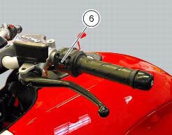
If the function is activated (see "lap activation/deactivation description), the lap time can be registered as follows: pressing the flash headlight button (6) the first time starts the "lap timer" for the first lap, and the dashboard shows the message "lap-start" flashing for 4 seconds, and then returns to the "previous" display; from this moment, each time that the flash (6) is pressed the display automatically shows the lap number and lap time for 10 seconds and then returns to the "previous" display.
You can save a maximum of 30 laps in the memory.
Once the memory is full, the dashboard no longer stores lap times when the flash headlight button (6) is pressed, and the flashing message "lap-full" is shown on the display for 4 seconds until the times are reset.
When the lap function is set disabled, the current "lap" is not stored.
If the lap function is active and suddenly the motorcycle is suddenly turned off (key-off), the function will be automatically disabled (even if the lap timer was active, the current "lap" is not stored).
If the time is never "stopped", it will roll over upon reaching 9 minutes, 59 seconds and 99 hundredths; the lap timer starts counting from 0 (zero) and will keep running until the function is disabled.
If however the lap function is switched on and the memory has not been cleared, but fewer than 30 laps have been saved (e.G. 18 Laps), the dashboard will store any remaining laps until the memory is full (in this case, it will store an additional 12 laps).
This function only displays the times for the lap being registered; but other data are also saved (max speed and max rpm) for viewing at a later date in the "lap data" function (stored lap display).
 Lap activation/deactivation function (lap time)
This function activates and deactivates the lap function (lap time).
To access the function it is necessary to view the ""setting" menu", using
buttons (1) "s" or (2) "t" select the "lap"
functi ...
 Stored lap display function
This function displays the stored laps.
To access the function it is necessary to view the ""setting" menu", using
buttons (1) "s" or (2) "t" select the "lap"
function and press the reset button ...
Other materials:
Swingarm
Swingarm pivot
Washer
Special screw
Bush
Sealing ring
Roller bearing
Special screw
Rear swingarm
Spacer
Bearing
Spacer
Spacer
Hose clip
Pin
Chain slider (lower)
Washer
O-ring
Calliper mounting bracket
Circlip
Spacer
Inner ring
Hub
Cable grommet
Ch ...
Exhaust system
Screw
Bush
Vibration damper mount
Silencer
Washer
Screw
Bracket
Nut
Nut
Upper heat guard
Screw
Washer
Central heat guard
Spacer
Clip nut
Long exhaust spring
Plug
Sealing washer, thickness 1
Vertical exhaust pipe
Lambda sensor
Nut
Vertical flange
Exh ...
Dashboard
Note
The dashboard is supplied as a single component; its internal components
cannot be renewed separately.
Important
Whenever the dashboard is renewed, the ignition key programming procedure
must be repeated.
Loosen the nuts (2) to remove the master dashboard (1) from its seat and
disconn ...