
Ducati Diavel Service Manual: Layout of engine control system and other components
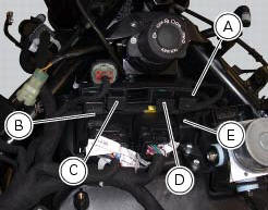
- Injection relay
- Etv relay (throttle valve operating engine)
- Fan radiator relay
- Hands free relay
- Ecu
 Inputs and outputs of engine control unit and connection to can network
The diagram illustrates the inputs and outputs for the engine control unit.
The signals from the brake buttons, the exhaust
by-pass valve command signal and the gear sensor signal are transmitt ...
 Removal of the control unit
Loosen the screws (1) and remove the relay supporting bracket (2), disconnect
the connectors (3) and remove the control
unit (4) from the vehicle.
...
Other materials:
Menu 2 on/off function
This function turns off and back on the menu 2.
If menu 2 is disabled, the functions for average fuel consumption (cons.Avg),
instantaneous fuel consumption (cons.),
Average speed (speed avg), trip time (trip time) and air temperature (air) will
no longer be displayed in the "main
screen". ...
Backlighting setting function for the instrument panel on Handlebar -
dashboard 2
This function allows backlighting setting of the instrument
panel on handlebar.
To access the function it is necessary to view the "setting" menu page 48, using
button (1, fig. 14) ?"
" or (2, fig. 14) ?" " select the "back light" function
and press ...
Description of the diagnosis instrument (dds)
The "dds" diagnostic system lets you diagnose any faults in the
injection-ignition system via a serial port. The system is
also equipped with functions to test various devices on the motorcycle. The dds
diagnosis instrument can be used to
measure current and voltage on any electrical device, t ...