
Ducati Diavel Service Manual: Location of elements on motorcycle
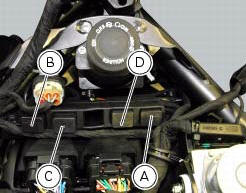
(A) injection relay; (b) etv relay (throttle valve operating engine); (c) radiator fan relay; (d) hands free relay.
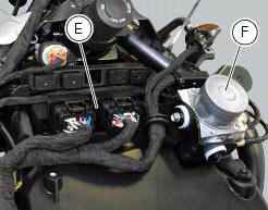
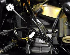
(E) ecu; (g) bbs (black box system or central electronics); (f) abs hydraulic unit with integrated control unit.
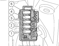
Fuses located at the rear left of the vehicle.
(1) 10A dashboard; (2) 5a engine control unit; (3) 15a key-sense; (4) 20a injection relay; (5) 15a throttle opening relay (etv).
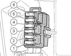
Fuses located at the rear right of the vehicle.
(1) 7.5A black box system (bbs); (2) navigator; (3) 25a abs 2; (4) 30a abs 1; (5) 10a fans; (6) 7.5A
Diagnosis/recharge
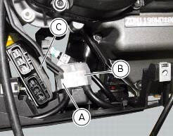
(A) starter motor relay; (b) main fuse (30a).
The voltage regulator (c) is mounted on the electrical components support.
 Electrical power for lighting and signalling devices
The front and rear running lights consist of led units with light conduits.
As a result, the light source is not visible as the
light is diffused through the surface of the light conduit.
...

Other materials:
Immobilizer override procedure
This procedure makes it possible to "temporarily" turn on
the motorcycle if the hf (hands free) system is not working.
Note
The pin code function must be activated by entering
your 4 digit pin in the instrument panel, otherwise the
vehicle cannot be turned on temporarily in the case ...
Front brake control
Front brake master cylinder
Brake lever
Special screw
Sealing washer
Screw
Phonic wheel
Brake disc
Pin
Left brake calliper
Boot
Bleed valve
Spare stand
Control unit - front callipers pipe
Microswitch
Oil duct union
Screw
Hose clip
Right brake calliper
Speci ...
Vehicle pre-delivery
Transport packaging integrity check (if required);
Removal from the transport packaging (if required);
Motorcycle integrity check;
Check of the supplied kit completeness (refer to the parts list supplied
together with the bike packaging);
Only if the bike is supplied in a crate: handle ...