
Ducati Diavel Service Manual: Low beam lights not working
Location of connections and components
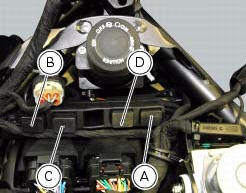
(A) injection relay; (b) etv relay (throttle valve operating engine); (c) radiator fan relay; (d) hands free relay.
Fuses located at the rear left of the vehicle.
(1) 10A dashboard; (2) 5a engine control unit; (3) 15a key-sense; (4) 20a injection relay; (5) 10a throttle opening relay (etv).
Fuses located at the rear right of the vehicle.
(1) 7.5A black box system (bbs); (2) 7.5A navigator/alarm; (3) 25a abs 2; (4) 30a abs 1; (5) 10a fans; (6) 7.5A diagnosis/recharge.
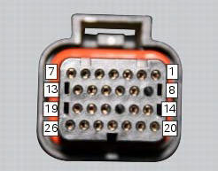
(A) low / high beam and parking light connections
 High beam lights not working
Fault codes
The hi beam light on the (slave) dashboard flashes at 1hz frequency.
Wiring diagram
Location of elements on motorcycle
(A) injection relay; (b) etv relay (throttle valve operating ...
 Horn not working
Fault codes
Dds: horn diagnosis -> short circuit to ground (s.C. Gnd).
Dashboard: the error "claxon" (horn) is shown on the service display. The eobd
warning light activates.
Wiring diagram
...
Other materials:
Riding style function (riding style change)
This function changes the motorcycle riding style.
Each riding style is associated with a different intervention level of the
traction control (dtc - ducati traction control) and
different engine power and output.
To change the motorcycle riding mode, press the reset button once
(3) and th ...
Belly fairing
Rh belly fairing
Lh belly fairing
Special screw
Nylon washer
Screw
Central belly fairing
Oil cooler shield
Special screw
Clip
Washer
Clip
Screw
Bracket
Screw
Spare parts catalogue
Diavel abs belly fairing
Diavel carbon
abs
belly fairing
Important
Bold refere ...
Hands free key (hf) not recognised
The activation of this (amber yellow) "warning" indicates that the hands free
system does not detect the active key (1,
fig.62) Near the vehicle.
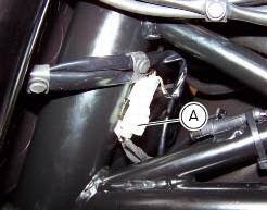
Note
Check that the active key (a) is near the vehicle (and has not been lost)
or that it works properly.
...