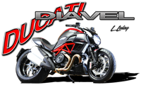
Ducati Diavel Owners Manual: Main components and devices
- Position on the vehicle
- Tank filler plug
- Side stand
- Passenger grabhandle
- Adjusting the front fork
- Adjusting the rear shock absorber
 Adjusting the position of the gearchange and rear brake
pedals
The position of the gearchange and rear brake pedals in
relation to the footrests can be adjusted to suit the
requirements of the rider.
Adjust the pedals as follows:
Gear change pedal (fig. 97) ...
 Position on the vehicle
Tank filler plug.
Seat lock.
Side stand.
Rear-view mirrors.
Front fork adjusters.
Rear shock absorber adjusters.
Catalytic converter.
Exhaust silencer (see "warning" on ...
Other materials:
Inputs and outputs of engine control unit and connection to can network
The diagram illustrates the inputs and outputs for the engine control unit.
The signals from the brake buttons, the exhaust
by-pass valve command signal and the gear sensor signal are transmitted over the
can line.
1I emergency engine cutout switch
2I start button
4I side stand button
6 ...
Helmet cable
Note
Helmet cable (2, fig. 104) Can be found inside the tool
kit, see "tool kit and accessories" on page 141.
Pass the cable through the helmet and insert the end of the
cable in the pin (3, fig. 104). Leave the helmet hanging and
refit the seat to hold it in place.
Warning
Th ...
Check the engine oil pressure
Note
The on-screen icons used during this procedure are explained in a table at
the end of this section.
To measure the pressure of the lubrication circuit, use the engine oil pressure
test point (19) as described below.
Disconnect the wiring connector (f) of pressure switch (1) and rem ...