
Ducati Diavel Service Manual: Number plate light not working
Fault codes
Dds: no fault code displayed.
Dashboard: no fault code displayed.
Location of connections and components
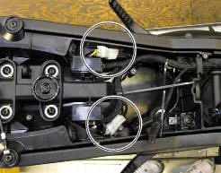
Location of rear turn indicator and number plate light connection.
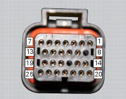
pin numbering for wiring harness side dashboard connector.
Checks
The number plate light receives pwm power supply from the dashboard. If necessary, power the number plate light with a 12 v external power supply to test function (connect correctly as indicated in the wiring diagram).
Check congruence of the ground connection on the number plate light.
Check the integrity of the electrical circuit and connections (short-circuits to ground, short-circuits to vdc, open circuits).
If none of the aforementioned tests identifies the problem, replace the dashboard.
Note
Check integrity of electric circuit - short-circuit to vdc = with dashboard on, using a voltmeter, a voltage is measured between the wire tested and ground.
Check integrity of electric circuit - short-circuit to ground = with the battery cables disconnected, using an ohmmeter, continuity is detected between the wire tested and ground.
Check integrity of electric circuit - open circuit = with the battery cables disconnected, using an ohmmeter, no continuity is detected between the two ends of the wire tested.
 High beam flash not working - start/stop lap function not working
Fault codes
Dds: no fault code displayed.
Dashboard: no fault code displayed.
Wiring diagram
Db dashboard connection, s high beam flash button. 7 Orange - o, 1
red/blue - r/b.
Location of ...
 Running lights not working
Fault codes
Dds: no fault code displayed.
Dashboard: no fault code displayed.
Location of connections and components
(A) low / high beam and parking light connections
rear running light and ...
Other materials:
Refitting the side stand
Place the stand plate on the rear shock absorber support; bring adjuster (14)
in line with bracket (s) and start the screw
(12) in the nut behind the bracket (s).
Insert the screws (11), (3) and (10) fully home in this order, but do not
tighten.
Loosen the screw (12) with the relative nut ...
Changing the coolant
Warning
This operation must only be carried out when the engine is cold.
Attempting to change the coolant with the engine hot
could lead to burns from hot coolant or scalding steam.
Place a container under the engine and place the motorcycle on its side
stand.
Remove the expansion reserv ...
Water pump
Screw
Washer
Circlip
Water pump outlet union
Bearing
bearing
Spacer
Aluminium gasket
Mechanical seal
Water pump impeller
Bush
Water pump cover assembly
Screw
Plug
Sealing washer
Generator cover
Special washer
Fuel filler flange
Spare parts catalogue
Diave ...