Ducati Diavel Service Manual: On-board computers and the can line
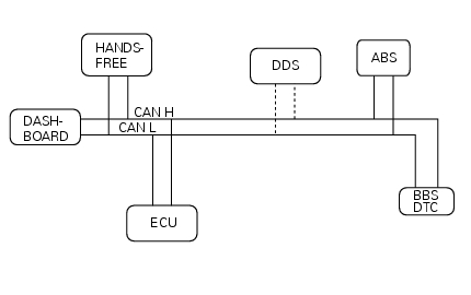
The following on-board computers make up the electrical system of the diavel and are connected with each other via the can line (or network):
- Master dashboard
- Slave dashboard
- Hands free (facilitated keyless start system)
- Ecu (engine control unit)
- Bbs (black box system or central electronics with integrated dtc traction control system.
- Abs (antilock braking system).

The drawing illustrates the network connecting the different computers ('nodes') on the diavel. The dtc system is not a separate unit and is integrated in the bbs.
The main characteristics of the computers used on the diavel are described as follows:
- The (master and slave) dashboard units not only display specific information of use to the rider, but are also connected to the sensors and actuators installed on the motorcycle. These units make the information received from the sensors available over the network and control the actuators, also in response to orders received from other computers connected to the network. The units' service displays also visualise any vehicle electronic system faults
- The hands free unit allows the rider to start the engine without
inserting a conventional key into the ignition switch.
This makes starting the motorcycle easier and quicker. The system also offers increased theft protection
- The ecu manages the functions of the engine and also controls the ride by wire system. The ride by wire system modulates throttle valve aperture via an electric actuator coordinated by the ecu. The ecu receives a "torque demand" signal from a potentiometer linked to the throttle grip. Three different throttle valve aperture regimens are stored in the ecu, which make different maximum power values and different torque curves possible.
- Like the dashboard units, the bbs is connected to sensors and actuators installed on the vehicle. The unit makes the information received from the sensors available over the network and controls the actuators, also in response to orders received from other computers connected to the network. It also has another fundamental function, as it gathers all the errors registered by the other computers due to specific faults. The software in the bbs also performs the dtc function, which regulates engine torque delivery to prevent wheelspin under acceleration.
The networked connection of the individual computers (nodes) creates a distributed system in which the nodes may communicate with one another and coordinate their actions by exchanging messages. This offers the following advantages:
- A distributed system needs less sensors, substantially simplifying the electrical system, as information provided by certain sensors may be shared, rendering it unnecessary to provide duplicate sensors for each node.
- Each node is capable of complex control functions on the basis of the information received from the other nodes connected to the network
- Reducing the number of connections and electrical wires makes the system more reliable.
The network allowing communication between the different nodes on the diavel is a serial (bus) type can (controller area network) network. Each node contains a circuit that can transmit and receive data to and from the network in accordance with priorities defined by specific bits included within the data itself (the message travelling over the network is always the one with the highest priority). As a result, the can bus network does not need to be managed with a specific centralised arbitration procedure that defines the priorities with which the elements connected to the network must communicate.
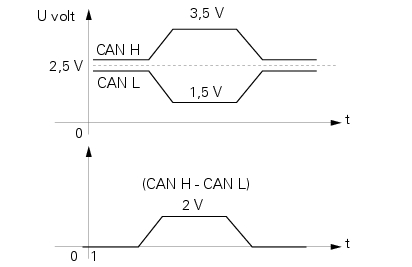
Each message travelling over the can network consists of a "train" of electrical impulses containing, as mentioned previously, the priority - in other terms the type of message - the data itself, the confirmation of reception and other data necessary for correct transmission and reception. The train of impulses is transmitted to the bus, which consists of two wires - can h and can l. Each node extrapolates the message and, as a result, the data contained, processing the Sequences of impulses received from on the can h and can l wires independently. This ensures superior reliability, as any interference in the electrical signals is effectively subtracted and eliminated.

One drawing shows the typical voltages on the can h and can l wires for each electrical impulse contained in the train "transporting" information shared by the nodes connected to the network. The other drawing shows the signal extrapolated by each node from the difference between the two former signals.
In short, the advantages of using the can bus are as follows:
- Only two wires are used (can h and can l)
- The architecture of the network independent from the configuration of the system or, in other terms, the number of nodes (computers) connected to the network itself
- The network is highly fault-tolerant
- The network is capable of handling node errors and/or faults effectively
- The network ensures reliable message delivery times by applying a priority system
Note that the control function for the electrical impulses travelling over the can network has no validity for diagnostic purposes, as the information contained in the trains themselves cannot be identified.
 Fault indication
The dds (diagnosis ducati system) indicates all active errors and all
inactive but stored errors gathered by the bbs. A
simplified summary of the active errors is also shown in the master dashboard ...
Other materials:
Refitting the primary drive gears and checking backlash
Fully degrease the crankshaft splined end and the corresponding spline on the
primary drive gear.
Position the spacer (c) onto the crankshaft.
Fit the driving gear (b) onto the crankshaft with the oil pump drive sprocket
facing the crankcase.
Temporarily secure the gear with the was ...
Checking valve lift
Set the engine to the configuration described for the "checking and adjusting
the valve clearances", previously indicated.
Position the tool 88765.1518 On the cylinder head: the part marked "a" should be
on the intake side and the part
marked "s" should be on the exhaust side.
Seat the pl ...
Engine setting function (engine power control)
This function customises engine power and output.
To access the function it is necessary to view the "setting" menu page 48, using
button (1, fig. 14) ?"
"or (2, fig. 14) ?" "select the "riding mode"function
and press the
reset button (12, fig. 12) T ...
