
Ducati Diavel Service Manual: On/off switch on handlebar
Introduction
The on/off switch on the handlebar is used to switch the dashboard on and off, if a key has been detected, and start the engine.
With the switch turned to "run off" (centre position), pushing downwards switches the dashboard on or off (activating the button inside the switch).
Wiring diagram
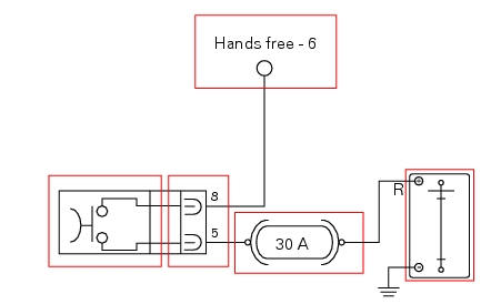
The button inside the on/off switch receives 12 volt power directly from the battery via the main 30 a fuse. When pressed, it sends the 12 volt power to the hands free system, which detects activation of the button. On/off switch pin 8, light blue wire (lb), on/off switch pin 5, red wire (r).

Pinout of right hand handlebar switch connection, wiring harness side.
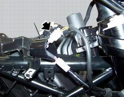
Location of the right hand handlebar switch connection.
Error codes
The hands free system generates no fault code in the event of a fault of the on/off switch on the handlebar.
Electrical characteristics and checking component
The switch receives 12 volt power directly from the battery via the main 30 a fuse.
Check for 12 volts on pin 5 of the switch.
Check for 12 volts on pin 6 of the hand free system side connector with the switched pressed. The voltage measured must be 0 volts when the switch is not pressed.
In the event of fault
In the event of a fault of the on/off switch on the handlebar, the button integrated into the hands free system may be used instead.
Installation location
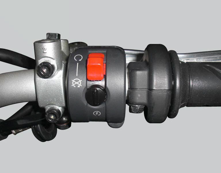
The image shows the location of the on/off switch, near the throttle grip on the right hand side of the handlebar.
 Communication antenna
Introduction
The communication antenna enables the hands free system to detect and
communicate with the active or passive key.
The active key is detectable within a range of 1.5 Metres, whereas ...
 The hands free relay
Introduction
This relay provides key on +15 power to all the devices on the motorcycle.
Functionally, it replaces the conventional
ignition switch.
Wiring diagram
The hands free relay receiv ...
Other materials:
Accelerator position sensor (throttle grip)
Introduction
An accelerator position sensor (aps) is mounted on the throttle body of the
diavel, which measures the degree of aperture
of the throttle grip.
The throttle grip is connected to the sensor via two metal cables
The sensor transmits information to the ecu relative to the "torque ...
Refitting the intake manifold and coolant union
Apply prescribed threadlocker to the fitting (12), start it with seal (24)
and tighten it to a torque of 2.5 Nm (min. 2 Nm -
max. 3 Nm) (sect. 3 - 3, Frame torque settings).
Install the pipe (b) and tighten the clamp (a) to the torque of 1 nm +/- 10%
(sect. 3 - 3, Engine torque settings).
...
Battery voltage indicator (battery)
This function describes the battery voltage indicator.
To access the function it is necessary to view the ""setting" menu", using
buttons (1) "s" or (2) "t" select the "battery"
function and press the reset button (3) to confirm.
The information will be displayed as follows:
if battery vol ...