
Ducati Diavel Service Manual: Operating principle
The ducati abs brake system manages the front and rear brakes separately. A pulse generator (phonic wheel), with a ring of slots, is fixed onto each wheel. On the left calliper mounting bracket of the front fork and on the rear brake calliper holder plate are hall effect sensors which detect the full sections and voids on the phonic wheel as the vehicle moves, providing and instantaneous wheel speed reading. These sensors transmit the data to the abs control unit, which contains software implementing a specific control algorithm developed by ducati. The software compares the average speed of the vehicle against the instantaneous wheel speed values to determine the degree of skidding. If the pressure applied to the calliper by the rider causes the control limits to be exceeded, the control unit intervenes in the braking circuit relative to the wheel for which incipient lock-up is detected. The abs modulates the calliper pressure with a system of solenoid valves that initially prevents any further increase in hydraulic pressure (ev valve closed), and then reduces pressure (av valve opened). The av valve is opened in a series of pulses (with less than 10 milliseconds between successive pulses), to reduce pressure in steps. When the wheel begins to rotate again in response to the diminished braking force applied and the wheel speed reaches the reference value, the av release valve is closed.
Simultaneously, the ev inlet valve is reopened, restoring normal operation of the brake system. The abs control unit can monitor and modulate brake force accordingly in the three following different conditions: dry road surface (high grip), wet or greasy road surface (poor grip) and uneven road surface. Abs functionality is disabled at vehicle speeds lower than 5 km/h.
A diagram illustrating how the abs system functions is given below.
The hydraulic component of the abs system consists of a primary circuit (from the cylinder to the control unit and from the control unit to the calliper) and a secondary circuit (completely within the control unit). The hydraulic layout of the abs system is given below.
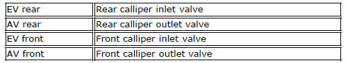
Key for abs hydraulic system layout

 Abs system operating information
The response of the system is based on the analysis of the speed signals for
front and rear wheels; the system is
automatically deactivated if either of these signals is missing.
Note
In the even ...
Other materials:
Passive key
Introduction
The passive key (1) is used when the active key is not working correctly or
is not available.
The passive key works as a transponder, and must therefore be placed physically
onto the antenna to work.
The mechanical part (2) of the key is used to open the seat or the tank plug ...
Solenoid starter
Remove the protection cover (a).
Undo the screws (2), taking care to collect the spring washers (3).
Remove the starter motor-solenoid cable (4) and the solenoid-battery cable (5).
Remove the starter solenoid (1) sliding it upwards.
Checking operation of the starter solenoid
To ...
Total distance covered indicator: "odometer"
This function shows the total distance covered by the vehicle (in km or miles
depending on the specific application).
At key-on the system automatically enters this function.
The odometer reading is stored permanently and cannot be reset.
If the distance travelled exceeds 199999 km (or 19 ...