
Ducati Diavel Service Manual: Overhauling the front wheel
Wheel bearings
Before checking the dimensions, check the wear on wheel bearings. Check for wear by hand after cleaning and degreasing the bearings in their seats.
Turn the inner race.
Check the amount of radial and axial play. Excessive play will cause vibration and make the bike unstable.
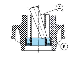
To remove the bearings (5) and the sealing rings (4) from the wheel hub follow the instructions below.
Position a drift (a) against the inner race of the bearing (5).
Tap with a hammer until knocking out the bearing (5).
Apply the drift at different points to keep the bearing square during removal.
Important
Once removed, the used bearings and sealing rings must not be refitted.
Before fitting new bearings, check that the housing is clean and free from scoring and damage.
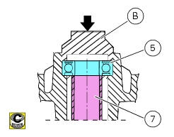
Grease the bearing seat and then push the new bearing into its seat.
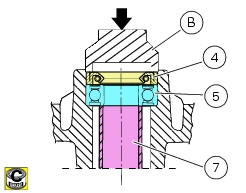
Using a tubular drift (b) that only bears on the outer race of the bearing, drive the bearing (5) fully into its seat.
Use the same method to install the sealing rings (4).
Ensure that spacer (7) is fitted between the two wheel bearings.
Note
Wheels must be rebalanced after repair, maintenance and overhaul operations.
Inspecting the wheel axle
Check the wheel shaft for straightness.
Turn the pin on a reference surface and measure maximum distortion using a feeler gauge (see sect. 3 - 1.1, Front wheel).
Overhauling the wheel
After you have checked the bearings, check the rim as follows.
Visually inspect the wheel for cracks, scoring and deformation; change the wheel if damaged.
Insert the shaft in the wheel and mount it on two fixed reference blocks.
Using a dial gauge, measure rim run-out and out-of-round relative to the pin axle (see sect. 3 - 1.1, Front wheel).
If the values measured are not within the tolerance limits, renew the wheel.
 Removal of the front wheel
Support the bike so that the front wheel is raised from the ground.
Remove the front brake calliper (b) by unscrewing the two screws (a) securing
the calliper to the fork leg; do not
disconnect ...
 Refitting the front wheel
When all the necessary inspections have been completed, refit the wheel as
follows.
Fit the spacers (3) and (9) to the seal rings on the sides of the wheel hub.
Install the complete whee ...
Other materials:
Introduction to the "hands free" system
The hands free system allows the rider to start the engine without physically
using the ignition key. The ignition key
merely has to be in the vicinity of the motorcycle, such as in the rider's
pocket, for example, in order to use the vehicle.
Compared to the standard ignition switches the h ...
Electrical components support
Clip
Screw
Voltage regulator
Battery fixing bracket
Battery support
Vibration damper mount
Hose clip
Vibration damper mount
Clip
Washer
Screw
Cover
Cable grommet
Battery
Battery mat
Screw
Bracket
Solenoid starter
Spring washer
Spacer
Screw
Horn
Scre ...
Stored lap erase function
This function erases the stored laps.
To access the function it is necessary to view the "setting" menu page 48, using
button (1, fig. 14) ?"" or (2, fig.
14) ?"" select the "lap" function and
press the reset button
(12, fig. 12) To go to next page.
...