
Ducati Diavel Owners Manual: Pre-ride checks
 Warning
failure to carry out these checks before riding, may lead to motorcycle damage and injury to rider and passenger.
Before riding, perform a thorough check-up on your bike as follows:
Fuel level in the tank
Check the fuel level in the tank. Fill tank if needed (page 140).
Engine oil level
Check the oil level in the sump through the sight glass.
Top up if needed (page 164).
Brake and clutch fluid
Check fluid level in the relevant reservoirs (page 143).
Coolant level
Check coolant level in the expansion reservoir.Top up if needed (page 142)
Tyre condition
Check tyre pressure and condition (page 162).
Controls
Operate the brake, clutch, throttle and gear change controls (levers, pedals and twistgrip) to check that they function correctly.
Lights and indicators
Make sure the lights, indicators and horn work properly.
Replace any burnt-out bulbs (page 158).
Key-operated locks
Ensure that fuel filler plug (page 118) and seat (page 119) are firmly secured.
Stand
Make sure side stand operates smoothly and is in the correct position
Abs light
After key-on, the abs light (9, fig. 4) Stays on. When the vehicle speed exceeds 5 km/h; the light turns off to indicate that the abs system is functioning properly.
 Warning
In case of malfunction, do not ride the motorcycle and contact a ducati dealer or authorised service centre.
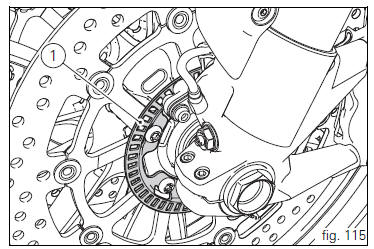
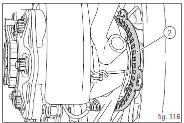
Abs device
Check that the front (1, fig. 115) And rear (2, fig. 116) Phonic wheels are clean.
 Warning
Clogged reading slots would compromise system proper operation.
It is recommended to disable abs system in case of muddy road surface because under this condition the system might be subject to sudden failure.
 Warning
Prolonged rearing could deactivate the abs system.
 Running-in recommendations
Maximum rpm (fig. 114)
Rotation speed for running-in period and during standard use
(rpm)
Up to 1000 km;
From 1000 to 2500 km.
Up to 1000 km
During the first 1000 km, keep an eye on the re ...
 Engine on/off
Warning
Before starting the engine, become familiar with the
controls you will need to use when riding (page 99).
Warning
Never start or run the engine indoors. Exhaust gases
are toxic and may ...
Other materials:
Refitting the shock absorber support
If you had removed them, apply recommended grease on the threads of the
adjusters (4) and the ring nuts (3) having
care not to have grease on the surface (c) of the adjusters.
Tighten the adjusters on the ring nut side opposite to that featuring flats
until bringing the surfaces as close as ...
Exhaust system
Screw
Bush
Vibration damper mount
Silencer
Washer
Screw
Bracket
Nut
Nut
Upper heat guard
Screw
Washer
Central heat guard
Spacer
Clip nut
Long exhaust spring
Plug
Sealing washer, thickness 1
Vertical exhaust pipe
Lambda sensor
Nut
Vertical flange
Exh ...
Tubeless tyres
Front tyre pressure:
2.50 Bar (rider only) - 2.6 Bar (with passenger and/or bags)
rear tyre pressure:
2.50 Bar (rider only) - 2.6 Bar (with passenger and/or bags)
as tyre pressures are affected by changes in temperature
and altitude; check and adjust them whenever you are riding
in areas where ...