
Ducati Diavel Service Manual: Reassembling the clutch
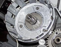
Position the spacer (13).
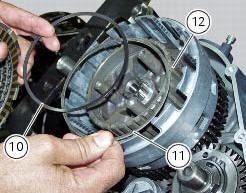
Fit the flat ring (11) and the belleville washer (10) on the clutch center (12), so that the convex side faces the clutch drum.
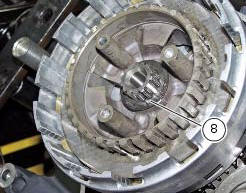
Locate the belleville washer (8).
Apply the prescribed grease to the thread of the gearbox primary shaft and the mating surface of nut (7), and fit it over belleville washer (8).
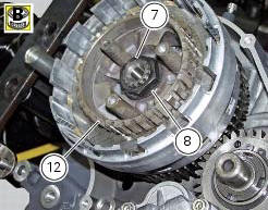
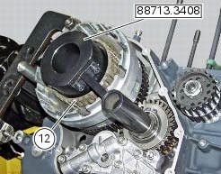
Lock the clutch center (12) by means of tool number 88713.3408 And tighten the retaining nut (7) to a torque of 190 nm (min. 180 Nm - max. 200 Nm) (sect. 3 - 3, Engine torque settings).
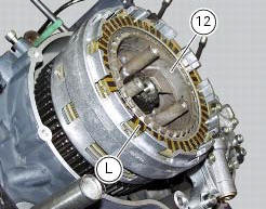
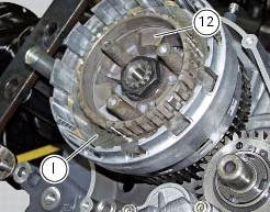
Install the clutch plates (9) in the following order: on the drum (12):
- A series of ten driving discs (l) alternately to new driven discs (i) thickness 2 mm;
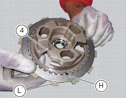
On the pressure plate (4):
- One driven disc (h), 2 mm thick;
- A driving disc (l).
Insert the control pin (14) in the bearing (5) and the latter in the gearbox primary shaft.
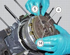
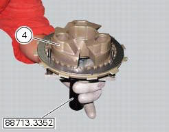
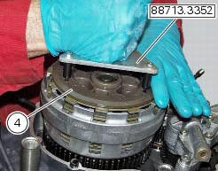
Place the pusher plate (4) with the two discs on the centring tool part no. 88713.3352.
Fit the pressure plate (4).
Insert a spring (3) in each slot.
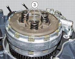
Position the o-ring (2).
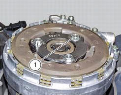
Lubricate the thread of the screws (1) with oil.
Insert the screws (1).
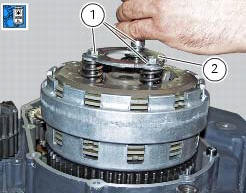
Tighten the screws (1) to a torque of 10 nm (min. 9 Nm - max. 11 Nm) (sect. 3 - 3, Engine torque settings).
 Checking and overhauling the components
Clearance between the clutch drum and friction plates
Insert a friction plate (e) in the clutch drum (f) and measure the clearance
(s) with a feeler gauge.
Clearance "s" must not exceed 0.6 Mm.
...
 Clutch cover
Clutch-side crankcase cover
Screw
Screw
Oil level sight glass
Screw
Plate
Bush
Sealing ring
Shim washer
Circlip
O-ring
Locating bush
O-ring
Plug
Sealing washer
Scr ...
Other materials:
Steering head: steering
Screw
Steering head
Screw
Lower rh u-bolt
Lower lh u-bolt
Bearing
Screw
Sealing ring
Washer
Spacer
Washer
Nut
Washer
Screw
Bottom yoke
Dowel
Nut
Screw
Special screw
Clip nut
Left-hand support
Front splashguard
Right-hand support
Front support
S ...
Refitting the timing belts
Rotate the pulleys on the timing belt driveshaft until the timing mark on the
outer roller is aligned with the mark on the
clutch-side crankcase cover.
In this condition, the horizontal cylinder piston will be at top dead centre.
Install in the alternator cover seat the tool code 88713.20 ...
General cleaning
To preserve the finish of metal parts and paintwork, wash
and clean your motorcycle at regular intervals, anyway
according to the road conditions you ride in. Use specific
products, where possible biodegradable. Avoid aggressive
detergents or solvents.
Use only water and neutral soap to clean ...