
Ducati Diavel Service Manual: Reassembling the frame and the lateral footrests
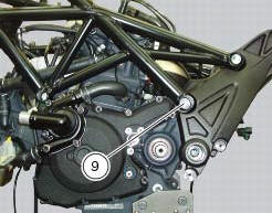
Apply the recommended grease to the thread of the pins (9) and of the nuts (8).
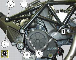
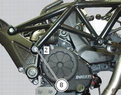
Place the frame (1) and the brackets (2) and (3) on the engine block. Start the pins (9) by holding the nuts (8) and insert without tightening the screws (6) into the adjusters (4).
Position and fix the rear shock absorber support to the engine crankcases and the swingarm brackets (sect. 7 - 12, Refitting the shock absorber support).
Tighten the screw (v) on the swingarm shaft right side to a torque of 72 nm +/- 5% (sect. 3 - 3, Frame torque settings), by holding the screw (z) on the left side.
Tighten the indicated front nut (8) to a torque of 60 nm +/- 5% (sect. 3 - 3, Frame torque settings), by holding the pin (9) on the left side.

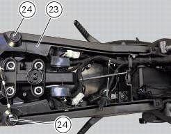
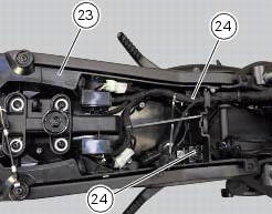
Reassemble the tool tray (23), as described in the following paragraph, by tightening the rear screws (24) to 14 nm +/- 5% (sect. 3 - 3, Frame torque settings).
Tighten the indicated rear nut (8) to a torque of 60 nm +/- 5% (sect. 3 - 3, Frame torque settings), by holding the pin (9) on the left side.
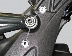
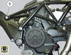
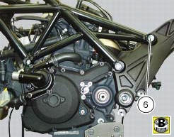
Work first on the left side and then on the right one, remove the special screws (6) and tighten to a torque of 0.5 Nm +/- 10% (sect. 3 - 3, Frame torque settings) the adjusters (4) and make sure they are fully home on the rear plates of the rear subframe.
Locate service tool no. 88713.3166 On the ring nut (5) and fit the torque wrench to the tool.
Hold the clearance adjusters (4) and tighten the ring nuts (5) to a torque of 100 nm +/-5% (sect. 3 - 3, Frame torque settings).
Lubricate thread and underside of special screws (6), then start them on the frame, and tighten them to a torque of 55 nm +/-5% (sect. 3 - 3, Frame torque settings).

Tighten the front screws (24) to a torque of 14 nm +/- 5% (sect. 3 - 3, Frame torque settings) that retain the tool tray (23).
 Reassembly of structural components and the frame
Check for the nuts with clips (8).
Apply recommended grease on the threads of the adjusters (4) and the ring
nuts (5) having care not to have grease on
the surface (c) of the adjusters.
Tig ...
 Reassembly of the tool tray
Place the tool tray unit (23) on the lateral brackets (2) and (3) by
tightening the screws (24) to 14 nm +/- 5% (sect. 3-3,
Frame torque settings).
If the handle guide (32) has been previously r ...
Other materials:
Oxygen sensors
Introduction
An on-off type oxygen sensor (in normal operating conditions, the voltage
generated by the sensors switches between a
value close to 1v and a value close to 0v) is mounted on each of the exhaust
manifold of the diavel.
Each oxygen sensor has its own internal heater, which recei ...
Warning indication (alarms/signals)
The instrument panel activates in real-time some warnings /
malfunction that are not dangerous for the correct operation
of the vehicle.
At key-on (at the end of the check) one or more "warnings"
are displayed if they are active.
When a "warning" is triggered, the indica ...
Refitting the engine
Refitting is the reverse of removal.
Important
Apply recommended grease and tighten the special screws (6) to a torque of
60 nm +/- 5% (sect. 3 - 3, Frame torque
settings).
Tighten the nuts (3) to a torque of 48 nm +/- 5% (sect. 3 - 3, Frame torque
settings).
Warning
For the assembly seque ...