
Ducati Diavel Service Manual: Reassembly of belly fairing
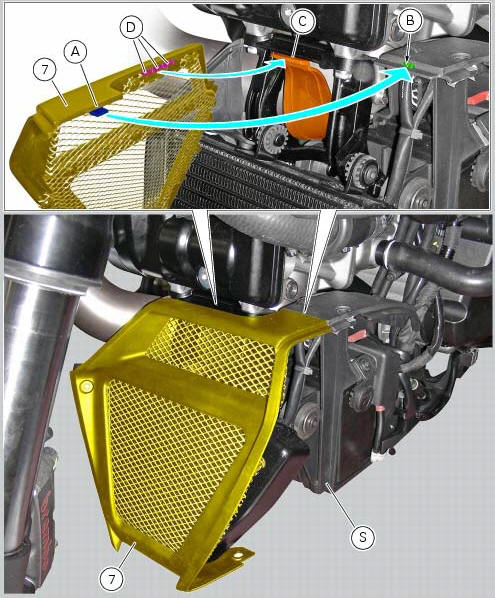
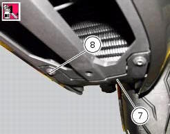
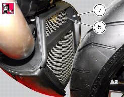
Position the oil cooler shield (7) inserting the tab (a) into the slit (b) in the electrical components support (s).
Note
On refitting, make sure that the tab (c) remains positioned under the retainers (d) of the shield (7).
Fit clips (11) on bracket (13) and orient them as shown in the figure.
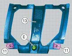
Apply rubber lubricant to the pin (e) of the bracket (13).
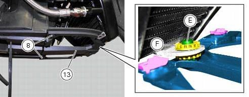
Insert pin (e) in the vibration damping pad (f) of the oil cooler.
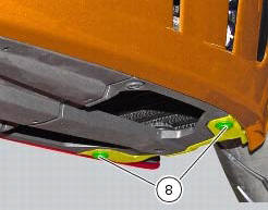
Fit the bracket (13) on the electrical components support, and tighten the screws (8) to a torque of 4 nm +/- 10 % (sect. 3 - 3, Frame torque settings).
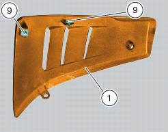
Fit clips (9) on lh belly fairing (2) and orient them as shown in the figure.
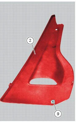
Put the lh belly fairing (2) in position by engaging slot (e) in the electrical components support, as shown in the figure.
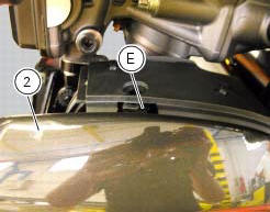
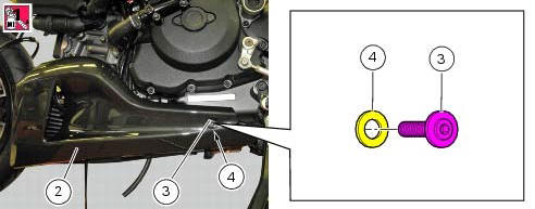
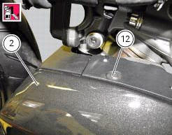
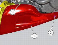
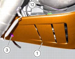
Apply recommended threadlocker on screws (3) and (12).
Fit the nylon washer (4) on the screw (3).
Fix the lh belly fairing (2) to the electrical components support by starting the screws (3) on the rear side, and the screw (12) on the upper side.
Apply recommended threadlocker to the screws (5) and (8).
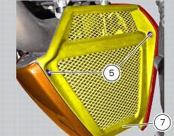
Fix the lh belly fairing (2) to the oil cooler shield (7) by starting the screw (8) on the lower side, and the screw (5) on the front side.
Fit the clips (9) on the rh belly fairing (1) orienting it as shown in the figure; follow the same procedure to refit the lh belly fairing (2).
Tighten to a torque of 4 nm +/- 10% (sect. 3 - 3, Frame torque settings) the screws (3), (5), (8) and (12) to fix the belly fairings (1) and (2) and the oil cooler shield (7).
 Removal of belly fairing
Loosen and remove the screws (5) and (8) that secure the oil cooler (7) to
the rh (1) and lh (2) belly fairings.
Remove the lh belly fairing (2) by loosening the screws (3) with relevan ...
 Electrical components support
Clip
Screw
Voltage regulator
Battery fixing bracket
Battery support
Vibration damper mount
Hose clip
Vibration damper mount
Clip
Washer
Screw
Cover
Cable grommet
Batte ...
Other materials:
Checking the engine timing
Set the engine to the configuration described for the "checking and adjusting
the valve clearances", previously indicated.
Install tool 88765.1188 (G) in the spark plug bore to determine the piston tdc,
the gauges (h) on the tool 88765.1518
And the timing check tool (degree wheel (l) 887 ...
Tips for use on the track
We recommend level 8 be used for a couple of full laps (to
allow the tyres to warm up) in order to get used to the
system. Then try levels 7, 6, etc., In succession until you
identify the dtc intervention level that suits you best (always
try each level for at least two laps to allow the tyres t ...
Removing the valves
Raise the rocker arm (3) and remove the opening shim (5) from the valves with
a pair of pliers.
Push down the closing rocker arms (16) and (4) and the closing shim (7).
Remove the half rings (6) from the valves with a magnetic screwdriver. Extract
the closing shims (7) from the valve ...