
Ducati Diavel Service Manual: Reassembly of rear shock absorber - rocker arm - linkage assembly
Once the needle roller bearings (9) have been removed from the rocker arm (18), upon reassembly fit a new needle roller bearing (9) on drift part no. 88713.1071 And lubricate with recommended grease.
Support the rocker arm and drive the needle roller bearings into the rocker arm bore until the tool seats against rocker arm.
Important
Introduce the needle roller bearings aligned with the hole to avoid any sticking: use a press, if necessary.
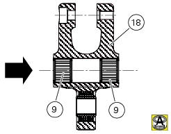
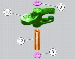
Insert one new seal (8) (with the metallic side faced outwards) into the drift and bring it fully home on the previously mounted roller bearing.
Repeat the above procedure for the other roller bearing (9) and the other seal (8).
Insert the inner spacer (13).
Position the linkages (10) and (12) on the rocker arm (18) by starting the screw (14).
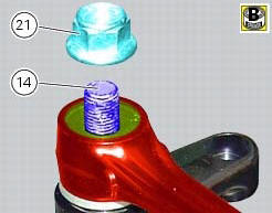
Apply grease to the threaded side of the screw (14) and to the contact face of the nut (21).
Start the nut (21) on the screw (14).
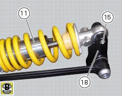
Tighten the nut (21) to a torque of 45 nm +/- 5% (sect. 3 - 3, Frame torque settings).
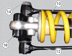
Apply grease to the thread and under the head of the screw (15) that secures the upper part of the shock absorber (11) and insert it in the rocker arm. Tighten the screw (15) to a torque of 45 nm +/- 5% (sect. 3 - 3, Frame torque settings).
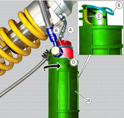
If the shock absorber reservoir covers have been removed, apply lubricant specific for rubber on the inner surface of the rubber cover (26). Fit the cover (26) on the shock absorber reservoir (a) and engage tab (b).
Note
Rotate the cover (26) until face (c) nearly contacts the fitting (d).
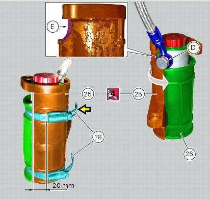
Apply recommended lubricant on the internal surface of the reservoir (25) support.
Position support (25) on the cover (26) and rotate support until face (e) nearly contacts the fitting (d).
Fix cover (26) and support (25) using ties (28), and position the ties so that the external profile of the retainers is about 20 cm away from the edge of support (25).
Note
The top tie (28) (yellow arrow) needs to be fully open in order to be positioned in its seat.
Fit
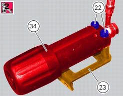
Fit the plate (23) on the preload adjusting knob (34) starting the screws (22) with the recommended threadlocker.
Tighten the screws.
 Disassembly of rear shock absorber - rocker arm - linkage assembly
Undo the screw (15) and remove the rear shock absorber (11) from the rocker
arm (18).
Undo
Undo the screw (14) and the nut (21) and remove the linkages (10) and (12)
from the rocker arm (1 ...
 Refitting the rear suspension
Lubricate the thread and underside of the special screw (1).
Insert the lower side of the shock absorber into the swingarm and insert the
screw (1).
Tighten the screw (1) to a torque of 45 nm ...
Other materials:
Removal of the expansion tank
Loosen the clamp (6), open the hose guide (a) and slide the hose (7) out of
the radiator.
Open clamps (14) and release the hoses that pass through them.
Loosen the screws (16).
Remove the tank (12) with its hoses (7) and (20) and the support (15).
Loosen the clamp (19) to r ...
Injection relay
Introduction
The fuel pump, injectors and ignition coils are all powered via the injection
relay. The relay also sends voltage to the
engine control unit, which enables activation of the relay itself.
Component assembling position
A injection relay; b etv relay (throttle valve actuator mot ...
Removal of the rear wheel eccentric hub and rear wheel shaft
Before removing the eccentric hub, you must first remove the parts listed
below.
Slacken off the screws (34).
Remove the spacer (20) and the inner ring (21) on the chain side and remove the
wheel shaft (31) with the brake disc
(30) from the opposite side.
Remove the circlip (19 ...