
Ducati Diavel Service Manual: Reassembly of structural components and the frame
Check for the nuts with clips (8).
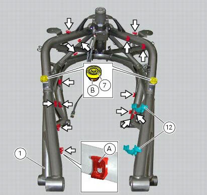
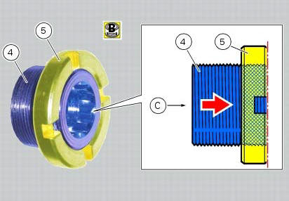
Apply recommended grease on the threads of the adjusters (4) and the ring nuts (5) having care not to have grease on the surface (c) of the adjusters.
Tighten the adjusters on the ring nut side opposite to that featuring flats until bringing the surfaces as close as possible as shown.
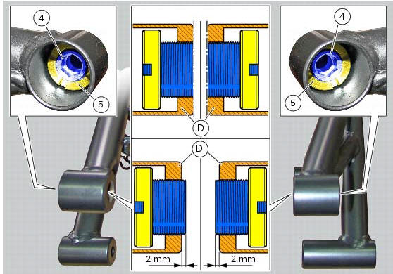
Start (form the frame external side) the adjusters (4) in the bushes (d) on frame (1).
Tighten to torque of 0.6 Nm +/- 10% (sect. 3 - 3, Frame torque settings) the adjusters (4), until they come out (on the opposite side) of at least 2 mm, as indicated.
Note
If at the specified torque the adjusters should not tighten properly, maybe the adjusters or the frame could be nonconforming.
Loosen the adjusters (4) until bringing the surfaces as close as possible to the bushes internal profiles (d), as shown.
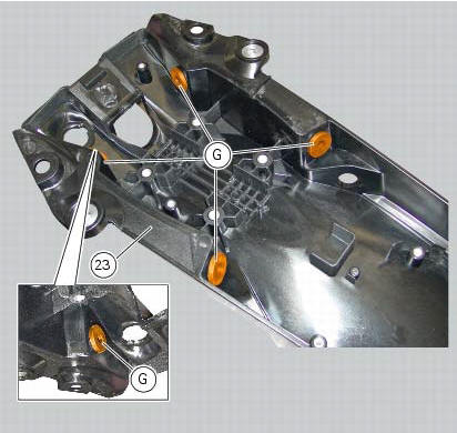
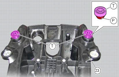
Check for the presence of rubber blocks (g) on the tray (23).
Note
In case of difficulties upon reassembly of the vibration damping pads (g), it is recommended to use specific lubricant suitable for rubber.
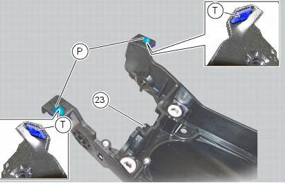
Check for the presence of the rubber pads (t) on the tray (23).
The pads are correctly fitted if the protrusions (p) come out completely on the insertion opposite side.
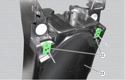
Check for the presence of clips (22) and make sure they are fitted aligned with the holes in the gloves compartment (23) front side, as shown in the figure.
Note
The threaded holes of the clips (22) must be perfectly aligned with the holes on the gloves compartment.
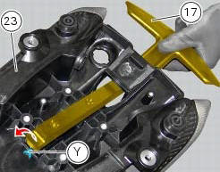
If removed, insert the rear handgrab (17) fully home through the opening in the gloves compartment (23) as shown.
Note
While inserting the component, make sure to push it past the stop tab (y) without hitting it.
Position the spacers (39) at the threaded inserts of the gloves compartment (23).
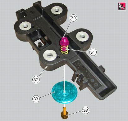
If previously removed, insert pin (30) on spring (31); position the spring (31), together with the pin (30), in the specific seat of the handle (32) guide as indicated.
Insert the screw (38) on knob (33), by orienting the latter as indicated.
Apply prescribed threadlocker on the screw thread (38).
Push down the pin (30) and start the screw (38) on the opposite side.
Tighten the screw (38) to a torque of 5 nm +/- 10% (sect. 3 -3, Frame torque settings).
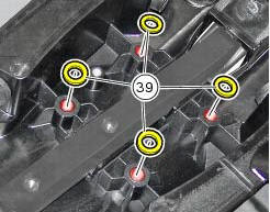
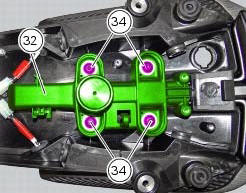
Fit block (32) starting the screws (34) and making sure that the spacers (39) stay in place, centred with the relative threaded inserts.
Tighten the screws (34) to a torque of 20 nm +/- 5% (sect. 3 - 3, Frame torque settings), following a cross-pattern sequence.
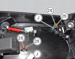
Place the clips (26) on the tabs (j), fix them starting the screws (25) and tighten the screws to the torque of 2 nm +/- 10% (sect. 3 - 3, Frame torque settings).
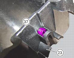
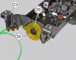
Position the nut (37) in the suitable seat on the compartment (23).
Fit the immobilizer antenna (36) as shown and tighten the screw (35) on nut (37) to the torque of 2 nm +/- 10% (sect. 3 - 3, Frame torque settings).
Fix the immobilizer antenna wire to the compartment using the three self-locking tie wraps.
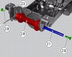
Start the screw (29) on the pin (21).
Place the tank supporting pad (28) in its seat on the gloves compartment (23) and insert the pin until bringing the screw (29) you started before fully home against the compartment (23).
Start the other screw (29) on the free end of the pin (21) and tighten the screw to a torque of 10 nm +/- 10% (sect. 3 - 3, Frame torque settings) holding the screw (29) on the opposite side.
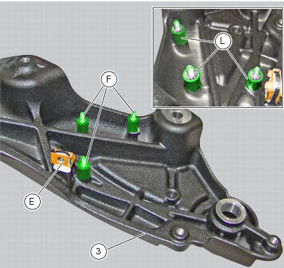
Check the presence of the clip (e) on the left plate of the rear subframe (3).
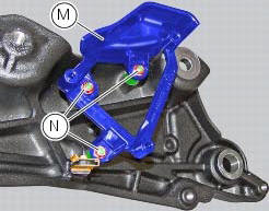
If the blackbox had been removed from the left plate of the rear subframe (3), on refitting start the silent blocks (f) on the plate (3) and tighten them until fully home. Insert the safety washers (l) on the threaded pins of the silent blocks (f).
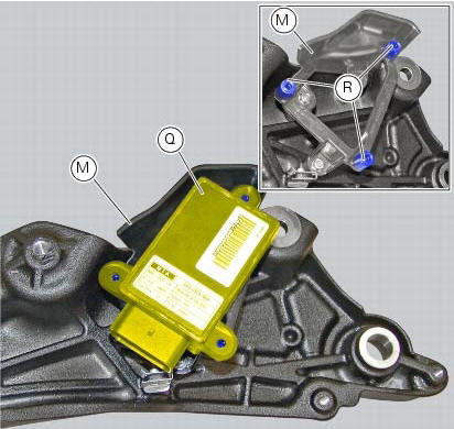
Fit the blackbox supporting bracket (m) starting the nuts (n). Tighten the nuts (n) to a torque of 2 nm +/- 10% (sect. 3 - 3, Frame torque settings).
Set the blackbox (q) on the stud bolts (r) of the blackbox supporting bracket (m).
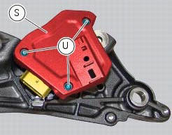
Fit the blackbox cover (s) starting the screws (u) and tighten the screws (u) to the torque of 3 nm +/- 10% (sect. 3 - 3, Frame torque settings).
 Checking the frame
Check the dimensions of the frame against the dimensions shown here to
determine whether it needs to be realigned or
renewed.
Important
Damaged frames must be changed, not repaired. Any work carr ...
 Reassembling the frame and the lateral footrests
Apply the recommended grease to the thread of the pins (9) and of the nuts
(8).
Place the frame (1) and the brackets (2) and (3) on the engine block. Start the
pins (9) by holding the nuts (8) ...
Other materials:
Tank filler plug
Note
To open or close the tank filler plug using the active
key, set the metal part in the middle position, as shown on
page 86.
Opening
Lift the cover (1, fig. 100) And insert the active or passive key
into the lock. Give the key a 1/4 turn clockwise to unlock.
Lift the plug (2, fig. 101) ...
Distance travelled on fuel reserve: trip fuel
This function shows the distance travelled on fuel reserve (in
km or miles depending on the specific application).
When the fuel light comes on, the display automatically
switches to the "trip fuel" indicator.
Trip fuel reading remains stored even after key-off until the
vehicle i ...
Hands free key (hf) not recognised
The activation of this (amber yellow) "warning" indicates
that the hands free system does not detect the active key
(1, fig. 62) Near the vehicle.
Note
In this case, ducati recommends checking that the
active key (1, fig. 62) Is near the vehicle (and has not been
lost) and that it f ...