
Ducati Diavel Service Manual: Reassembly of the crankcase halves
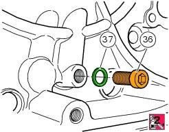
If removed, apply threadlocker on the screw (36), insert it with the washer (37) on the crankcase half and tighten it to The torque of 8 nm (min. 7 Nm - max. 9 Nm) (sect. 3 - 3, Engine torque settings).
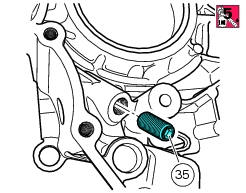
If removed, apply threadlocker on the dowel thread (35), tighten it to a torque of 20 nm (min. 18 Nm - max. 22 Nm) (sect. 3 - 3, Engine torque settings).
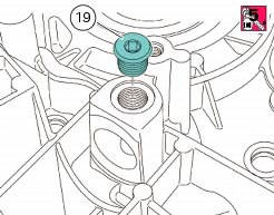
If removed, apply threadlocker on the plug (19), and tighten it to a torque of 24 nm (min. 21 Nm - max. 27 Nm) (sect. 3 - 3, Engine torque settings).
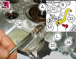
Install the o-ring (32) on its seat (a) in the crankcase half. Fit the pipe (33) in the crankcase half, inserting the end (b) fully in the o-ring. Align the hole (l) of the pipe with the threaded hole (m) in the crankcase half. Apply threadlocker to the screw (34) and start it in the threaded hole (m). Tighten the screw to a torque of 8 nm (min. 7 Nm - max. 9 Nm) (sect. 3 - 3, Engine torque settings).
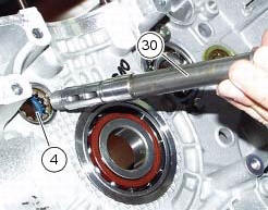
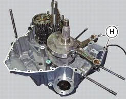
Install the timing belt driveshaft (30) in the roller bearing (4) in the clutch-side crankcase half.
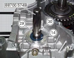
To avoid damaging the oil seal (14) on the timing belt driveshaft, protect the threaded end of the shaft with the special protective cap 88700.5749. Dampen oil seal (14) with alcohol and fit it on the timing layshaft. Push seal until it contacts the roller bearing (4).
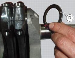
Fit the circlip (29) in the groove on the shaft and remove the protective cap.
Note
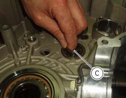
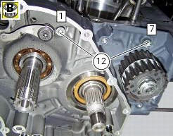
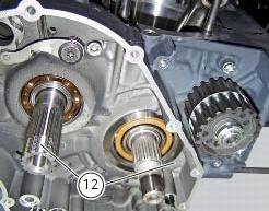
When refitting used components, before installing the gearbox assembly in the crankcase half, make sure that the inner races (c) of the gearbox shaft bearings are fitted into the correct bearings and have not been left on the shafts.
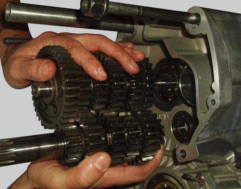
Match gearbox shafts, fit the shims and fit them to the clutch-side crankcase half.
Note
A table and a list of the gearbox components appear in sect. 9 - 7.2, Reassembly of the gearbox shafts.
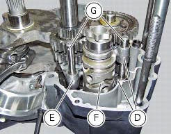
Insert the forks of 1st- 4th and 2nd- 3rd speed (d) in the corresponding sliding slots of the secondary shaft driven gears and insert the pin (g) in the forks: the two forks must be fitted with the number that indicates the gear facing upwards.
Note
The two selector forks are identical.
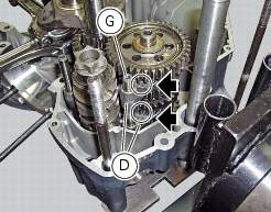
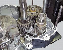
Insert the fork of 5th- 6th speed (e) in the primary shaft driven gear and the pin (g) in the fork (e): the fork must be fitted with the number indicating the gear facing the crankcase half.
Position the pin (g) of the forks (d) in the crankcase half. Holding the gear lever claw, position the gear drum (f) in the crankcase half.
Position the pin (g) of the fork (e) in the crankcase half.
Install the crankcase with calculated shims in the crankcase half bearing: the shims (r) of the shaft must be placed with the chamfering facing the shaft. Position the connecting rods (h) matching the corresponding seats of the cylinder.
Important
Make sure that the connecting rods (h) are correctly positioned in the cylinders. Incorrect positioning of the connecting rods at this stage will inevitably lead to the need to re-open the crankcase halves.
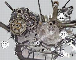
Check that the two locating bushes (22) are correctly fitted.
Grease the o-ring (31) to hold it in position and install it.
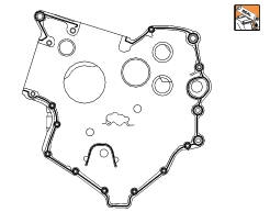
Apply a uniform and continuous bead of ducati liquid gasket to the mating surfaces of the crankcase halves, going around all the holes as shown in the figure.
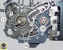
Bring the crankcase halves (3) and (13) together, tapping with a rubber mallet in the area of the shafts if necessary.
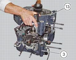
Apply the recommended grease to the screws and insert them in the crankcase
halves (note that the screws are different
lengths). Start with the larger diameter screws (m8), and follow the order
indicated. 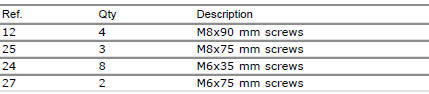
Tighten all screws to the torque indicated below (sect. 3 - 3, Engine torque settings):
- Screws (12) and (25) to a preload of 19 nm (min. 17 Nm - max. 21 Nm) and
then a torque of 25 nm (min. 22 Nm - max.
28 Nm);
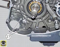
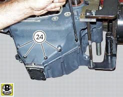
- Screws (24) and (27) to a torque of 10 nm (min. 9 Nm - max. 11 Nm).
Check that the crankshaft can be turned with a certain amount of interference with the main bearings (the crankshaft should have a pre-load of 0.20 To 0.30 Mm); check also that all the parts you have fitted are free to rotate or move correctly.
Install the cover to reach the mesh filter (sect. 4- 3, Changing the engine oil and filter cartridge).
Install the cartridge filter (sect. 4 - 3, Changing the engine oil and filter cartridge).
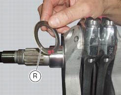
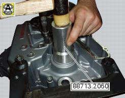
Fit the sealing ring (8) on the gear secondary shaft with side (l) to the engine side.
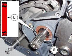
Install the bushing of the tool with code 88713.2060 On the secondary shaft. Lubricate the new ring (8) and seat it.
Using the tool's drift, drive the sealing ring fully home so it seats against the crankcase half bearing.
 Shimming the shafts
Before assembling the crankcase halves, calculate the shims required to
obtain the correct end float of the crankshaft and
gearbox shafts.
To determine the correct shim thickness proceed as foll ...
 Crankshaft/connecting rods assembly
Special screw
Connecting rod assembly
Half bearing
Grub screw
Bushes
Crankshaft
Grub screw
Shim washer
Spare parts catalogue
Diavel abs connecting rods
Diavel carbon
abs
co ...
Other materials:
Final drive
Circlip
Nut
Washer
Nut
Rear sprocket flange
Cush drive bush
Inner ring
Chain
Spacer
Chain cover
Screw
Nut
Lock washer
Front sprocket
Spacer
O-ring
Rear sprocket
Spare parts catalogue
Diavel abs gearbox
Diavel abs rear wheel axle
Diavel carbon
abs
gearbo ...
Changing bulbs
Changing the headlight bulbs
Before replacing a burnt out light bulb, ensure that the replacement bulb has
the same voltage and power rating as
specified for the lighting device in question (sect. 3 - 1.1, Lights/instrument
panel).
Warning
The halogen light bulbs in the headlight become hot ...
Refitting the number plate holder
Place the number plate light (5), as indicated, on the number plate holder
plate (8) and tighten the screws (7) to a torque
of 2 nm +/- 10% (sect. 3 - 3, Frame torque settings).
Thread the number plate light wiring (c) into the opening in the number plate
holder plate as shown.
Fit ...