
Ducati Diavel Service Manual: Reassembly of the gearbox shafts
Figure 1 shows all the parts to be reassembled on the gearbox primary shaft (2), with the calculated end shims (1) and (11) (sec. 9 - 9.2, Reassembly of the crankcase halves).
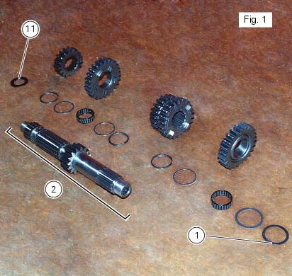
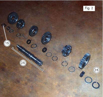
Figure 2 shows all the parts to be installed on the gearbox secondary shaft (25), with calculated end shims (15) and (26) (sec. 9 - 9.2, Reassembly of the crankcase halves).
Reassemble the gears on the gearbox shafts by reversing the disassembly procedure.
Take particular care when installing the idler gears. The assembly of the 3rd and 4th speed gears and the relative fixing components on the secondary shaft is given as an example.
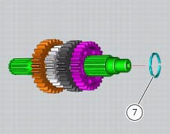
Fit the circlip (7), checking that it is fully inserted into its groove on the shaft. Push the circlip into position with a suitable size tubular drift.
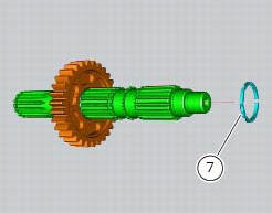
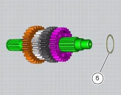
Slide the washer with three internal points (6) over the shaft until it locates against the circlip you have just fitted.
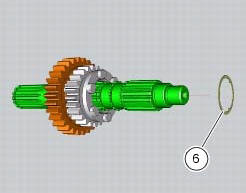
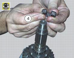
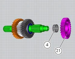
To fit the needle roller cage (4) onto the shaft, first lubricate it with plenty of grease (of recommended type) and then open it slightly to make it easier to slide on to the shaft.
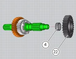
Fit the 3rd speed gear (22).
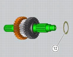
Fit on the gear the three-pointed washer (12), which can be distinguished from its counterpart (6) by its bigger outside diameter.
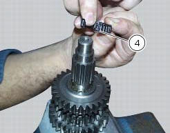
Fit another needle roller cage (4) using the method already described.
Fit the 4th speed gear (21).
Fit another safety washer (6) and another circlip (7) into the shaft. Push it inside its seat using the previously used pad.
 Inspection of the gear selector drum
Use a gauge to measure the clearance between fork pin and the slot on the
selector drum.
If the service limit is exceeded, determine which part must be replaced by
comparing these dimensions wi ...
 Reassembly of the gearbox
To refit the gearbox components follow the procedure under sect. 9 - 9.2,
Reassembly of the crankcase halves, relating to
reassembly of the engine crankcase.
As a final practical test, ensure th ...
Other materials:
Removal of the cylinder/piston assembly
Loosen the clamps (7) and remove the hoses (8) and (9) from the cylinder
barrels (10) and from the alternator-side
crankcase cover.
If damaged, unscrew the unions (6).
Note
The following procedure is described with the engine removed from the
frame and the cylinder head r ...
Setting menu
This menu is used to enable/disable and set some
motorcycle functions.
To access the "setting menu" press the button (2, fig. 14)
? for 3 seconds.
Note
When within this menu no other function can be
displayed.
Important
For safety reasons, the setting menu can only be
ac ...
Disassembly of rear shock absorber - rocker arm - linkage assembly
Undo the screw (15) and remove the rear shock absorber (11) from the rocker
arm (18).
Undo
Undo the screw (14) and the nut (21) and remove the linkages (10) and (12)
from the rocker arm (18).
The rocker arm movement is obtained by needle roller bearings (9) rotating on
a spacer (1 ...