
Ducati Diavel Service Manual: Reassembly of the oil pump
Check that the circlip (3) and tongue (13) are present on the pump.
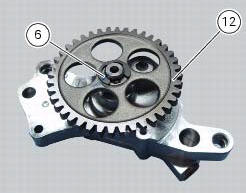
Fit the pump drive gear (12) on to the oil pump and secure it by installing the circlip (6) in its groove.
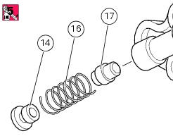
Insert the by-pass valve pump (17), the spring (16) and screw the plug (14). Tighten the plug (14) to a torque of 17 nm (min. 15 Nm - max. 19 Nm) (sect. 3 - 3, Engine torque settings) applying a medium strength threadlocker.
 Disassembly of the oil pump
Hold the oil pump (1) in a vice taking care not to damage the drive gear
(12).
Warning
Make sure that vice jaws are faced with soft material.
Remove the plug (14) and extract the spring (16) ...
 Refitting the oil pump
If removed, apply specific threadlocker on the bushing (7) outer thread, and
screw it in the crankcase half, observing the
height.
Position the reference bushings (15) and the oil sealing o-ri ...
Other materials:
Adjusting the throttle cable
The throttle grip in all steering positions must have free play, measured on
the periphery of the flange of the grip, of 1.5 -
2.0 Mm.
If necessary, adjust using the adjusters (1) and (2) located on the steering
tube on the right side of the motorcycle.
Adjuster (1) adjusts the throttle o ...
Check the idle and the co amount with warm engine
Start the engine;
Switch on the dds and check that it does not signal any error (otherwise
consult the relevant paragraph of this manual
to reset the error and proceed with the idle check);
Enter the "self diagnosis" menu by selecting the diavel model in the
available vehicle version. ...
Radiator fan relay
Introduction
The radiator fans are powered via a specific relay, which is enabled by the
engine control unit.
Component assembling position
A injection relay; b etv relay (throttle valve actuator motor), c radiator
fan relay, d engine control unit.
Location of right hand fan connecti ...