
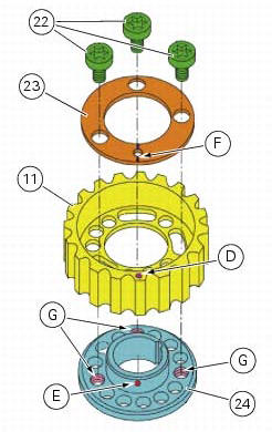
Ducati Diavel Service Manual: Reassembly of the timing pulleys
Fit the pulley (11) on the flange (24), aligning the timing mark (d) on the pulley with the timing mark on the (e) on the flange.
Install the washer (23) up against the pulley, aligning the timing notch (f) with the timing marks on the pulley and the flange.
Insert the three screws (22) in the threaded holes (g) of the flange.
Tighten the screws (22) to a torque of 10 nm (min. 9 Nm - max. 11 Nm) (sect. 3 - 3, Engine torque settings).
 Refitting the idler and tensioner pulley mounting studs
Apply the recommended threadlocker to the threads of the studs.
Insert the tensioner pins (12) on the cylinder heads, and tighten them using the
tool code 88713.1821.
Tighten the tensioner pin ...
 Refitting the cylinder heads pulleys/fixed tensioners
Check that the keyway on the end of the camshaft is in good condition and
without burrs.
Fit a woodruff key (b) in the keyway of each camshaft.
Fit the pulley (11) on the camshaft, inserti ...
Other materials:
Chain lubrication
The chain fitted on your motorcycle has o-rings that keep dirt
out of and lubricant inside the sliding parts.
So as not to damage these seals when cleaning the chain,
use special solvents and avoid aggressive washing with highpressure
steam cleaners.
After cleaning, blow the chain dry with ...
Adjusting the throttle cable
The throttle grip in all steering positions must have free play, measured on
the periphery of the flange of the grip, of 1.5 -
2.0 Mm.
If necessary, adjust using the adjusters (1) and (2) located on the steering
tube on the right side of the motorcycle.
Adjuster (1) adjusts the throttle o ...
Overhaul of the flywheel-alternator assembly
Examine the inner part of alternator rotor (24) for signs of damage. Check
that the starter clutch is working properly and
that the needle races do not show signs of wear or damage of any kind. If there
is any malfunction, remove the whole
assembly.
Disassembling the generator flywheel
U ...