
Ducati Diavel Service Manual: Reassembly of the tool tray
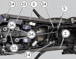
Place the tool tray unit (23) on the lateral brackets (2) and (3) by tightening the screws (24) to 14 nm +/- 5% (sect. 3-3, Frame torque settings).
If the handle guide (32) has been previously removed, position it on the tray (23) and tighten the screws (34) to 20 nm +/- 5% (sect. 3-3, Frame torque settings).
Reposition the wiring branch in the seat (s) in the tray (23).
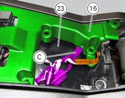
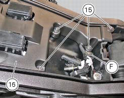
Place the gloves compartment cover (16) on gloves compartment (23), inserting wiring (c) into the suitable recess in the cover (16).
Warning
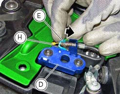
While positioning the cover (16) on the compartment (23), push bracket (e) of the lock latch (d) in the direction shown by the arrow, to prevent the lock wire terminal (h) from being squeezed under the cover.
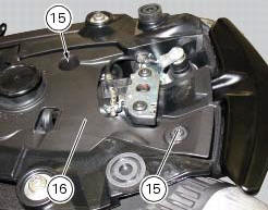
Check the presence of the clip (f) on the cover (16).
Fix the cover (16) by tightening the screws (15) to a torque of 4 nm +/- 10% (sect. 3 -3, Frame torque settings).
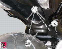
Apply the recommended threadlocker to the screws (40).
Reposition the splashguard (20) and tighten the screws (40) to a torque of 4 nm +/- 10% (sect. 3 -3, Frame torque settings).
 Reassembling the frame and the lateral footrests
Apply the recommended grease to the thread of the pins (9) and of the nuts
(8).
Place the frame (1) and the brackets (2) and (3) on the engine block. Start the
pins (9) by holding the nuts (8) ...
 Tail light - number plate holder
Rh tail light
Vibration damper mount
Spacer
Screw
Number plate light
Screw
Screw
Plate
Number plate holder
Nut
Screw
Rear chain guard
Lh tail light
Spring washer
Vib ...
Other materials:
Removal of the fuel tank filler cap
Remove tank covers (sect. 5 - 2, Removal of the fuel tank fairings).
Remove hoses (8) and (15) from the filler cap assembly (10).
Open the filler cap.
Unscrew the outer screws (17) securing the ring nut to the filler cap recess.
Remove the filler cap assembly (10).
...
Engine setting function (engine power control)
This function customises engine power and output.
To access the function it is necessary to view the ""setting" menu", using
buttons (1) "s" or (2) "t" select the "riding
mode" function and press the reset button (3) to enter the following page.
Use button (1) "s" or (2) "t" to select the r ...
Coolant temperature
This function indicates coolant indication state.
The temperature unit of measure can be selected (C or f).
The reading is indicated as follows:
If the reading is between - 39C and +39C "lo" is
shown flashing on the instrument panel (steady);
If the reading is between +40C an ...