
Ducati Diavel Service Manual: Recovery procedure in the event of hands free system fault
If the hands free system can no longer communicate with the other control
units over the can network (with the
dashboard or engine on), the following icon is shown on the tank dashboard:
The following image shows the icon appearing on the tank dashboard: this
indicates that the hands free system is not
connected to the can network or that it cannot communicate over the can network
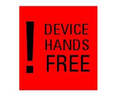
in the event of a hands free system fault, the following icon is displayed on
the tank dashboard: 
The following image shows the icon appearing on the tank dashboard: this indicates a hands free system fault if the engine was off before the fault occurred, starting the engine may not be possible.
If the engine was running before the fault occurred, the hands free system will not switch the engine off. Once the engine is switched off, however, starting the engine may no longer be possible.
 Recovery procedure in the event of electric steering lock fault
If any fault occurs during activation of the electric steering lock: for
example, if the pin jams, if the handlebar is moved
while the pin is deployed or if there is excessive strain on the electri ...
 Start procedure with pin code (no keys)
The motorcycle may be started without keys with a special procedure using the
dashboard and the switches on the
handlebar.
Note
This procedure is only possible if the pin code has been enabled
...
Other materials:
Refitting the alternator-side crankcase cover
Before the assembly make sure that the water pump unit is fitted on the
generator cover (sect. 9 - 3.3, Refitting the
water pump).
If bearing (27) has been removed, lubricate its seat with specified grease to
fit it on the generator cover (13).
Fit bearing completely in its seat and orien ...
Removal of the rear brake calliper
Important
The brake manufacturer advises against any servicing of the internal
components of brake callipers or the master cylinder.
Incorrect overhaul of these critical safety components can endanger rider and
passenger safety.
Before removing the parts in question, you must first carry ou ...
Fuel tank
fuel tank
Rubber pad
Spacer
Screw
Hose
Tray
Y-fitting
Hose
Hose
Filler cap
Screw
Complete hose guide
Screw
Hose clip
Hose
Screw
Screw
Sealing washer
Screw
Flange
Sealing washer
Spare parts catalogue
Diavel abs fuel tank
Diavel abs fuel system
Diav ...