
Ducati Diavel Service Manual: Rectifier-regulator
The rectifier (1) is placed in the electrical components compartment.
The rectifier/regulator consists of an aluminium casing containing the diodes that rectify the current produced by the alternator. It also contains an electronic device that regulates the current supplied by the alternator in accordance with battery voltage.
If the battery is drained, the current has the value necessary to restore optimum operating conditions of the battery. In contrast, if the battery is fully charged, the current value will be lower.
Note
Control the charger current by using the dds diagnosis instrument (sect. 6 - 11, Diagnostic instruments).
Removal of the regulator 
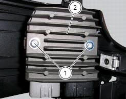
Undo the two fixing screws (1) of the voltage regulator (2) and remove it together with them.
Important
Do not disconnect the battery cables when engine is running because this would cause irreparable damage to the regulator.

Refitting the regulator
Position the regulator (1) on the support.
Tighten the screws (1) to a torque of 10 nm +/- 10% (sect. 3 - 3, Frame torque settings).
Important
Do not disconnect the battery cables when engine is running because this would cause irreparable damage to the regulator.
Regulator fuse
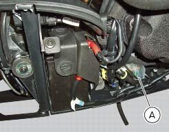
The 30 a fuse is located inside the solenoid starter in the electrical components compartment.
Remove the fuse cap (a) to reach it.
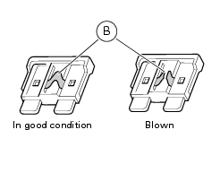
A blown fuse can be identified by breakage of the inner filament (b).
Important
To avoid possible short circuits, replace the fuse in key off condition.
Warning
Never use a fuse with a rating other than the specified value. Failure to observe this rule may damage the electric system or even cause fire.
 Alternator
It is equipped with a 12 v, 430 w generator, consisting of a fixed element
(stator, a) located on the generator cover and
of a movable element (rotor, b) fixed to the crankshaft.
Note
To chec ...
 Electric starting system
Note
The references of the elements listed below are those of the "wiring
diagram", sect. 6 -1.
Electric starting system
The key components of the electric starting system are a solenoid (6) and ...
Other materials:
Reassembly of rear shock absorber - rocker arm - linkage assembly
Once the needle roller bearings (9) have been removed from the rocker arm
(18), upon reassembly fit a new needle roller
bearing (9) on drift part no. 88713.1071 And lubricate with recommended grease.
Support the rocker arm and drive the needle roller bearings into the rocker arm
bore until t ...
Refitting the water pump
Clean the seat on the cover, any parts you intend to reuse, and the impeller
shaft. Then refit as follows.
Fit on the impeller (10) shaft the mechanical seal (9) as indicated in the
figure.
Apply specified lubricant to facilitate the insertion.
Bring the mechanical seal fully home on th ...
Front brake control
Front brake master cylinder
Brake lever
Special screw
Sealing washer
Screw
Phonic wheel
Brake disc
Pin
Left brake calliper
Boot
Bleed valve
Spare stand
Control unit - front callipers pipe
Microswitch
Oil duct union
Screw
Hose clip
Right brake calliper
Speci ...