
Ducati Diavel Service Manual: Refitting the abs control unit
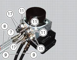
If the brake hoses (7), (8), (9) and (10) on the abs control unit are changed or removed, ensure that the fittings on the control unit are positioned correctly.
Warning
If incorrectly positioned, the hose can affect brake operation and foul moving parts. Position the hose as shown in the figure.
Pipes (7), (8), (9) and (10) fixing must be carried out by placing new gaskets (11) between the couplings.
Tighten the screws (17) to the torque of 23 nm +/- 10% (sect. 3 - 3, Frame torque settings).
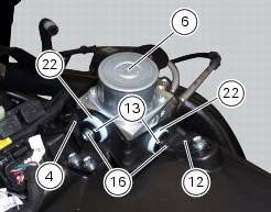
Check that there are vibration dampers (22) and spacers (13) on the abs supporting bracket (12).
Refit the abs control unit (6) on the supporting bracket (12), and fix it by starting and tightening the retaining screws (16) to a torque of 10 nm +/- 10% (sect. 3 - 3, Frame torque settings).
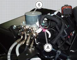
Connect the connector (a) of the abs control unit (6).
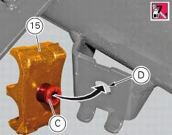
If removed, refit the front rubber pad (15) applying the recommended threadlocker to the pin (c) and the rear face of the pad. Fit the pad inserting pin (c) into the corresponding hole (d).
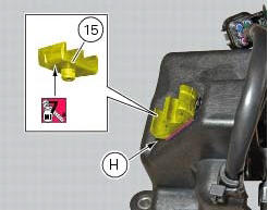
If removed, refit the rear rubber pad (15) applying the recommended threadlocker to the cover of the exhaust valve motor until achieving engagement.
Note
The rubber pad (15) must be aligned with the corresponding reference notch (h) as shown.
To fill up the system, carry out the instructions for replacement of fluid of the front and rear braking system master cylinder or calliper to which the pipe is connected (sect. 4 - 3, Changing the brake fluid).
Important
If the abs control unit is replaced, this must be supplied with secondary circuit already full of fluid; the control unit must Be fitted and the system filled and bleeded as a traditional system.
 Removing of the abs control unit
Drain the hydraulic fluid that is inside the front and rear braking system
tubes by disconnecting them from the master
cylinder and the calliper (sect. 4 -3, Changing the brake fluid).
Disco ...
 Flexible wiring/hoses positioning
The routing of the abs wiring has been optimised to ensure the minimum
obstruction.
Each section is designed to prevent interference with parts that might damage
wires or cause operating failur ...
Other materials:
Oil pump
Complete oil pump assembly
O-ring
Circlip
O-ring
Pump body
Circlip
Reducer bush
Spring washer
Screw
Screw
Spring washer
Pump drive gear
Key
By-pass plug
Locating bush
By-pass spring
By-pass valve
Spare parts catalogue
Diavel abs filters and oil pump
Diavel ...
Checking and topping up coolant level
Check coolant level in the expansion tank on the right side of
the vehicle.
Steer the handlebar completely to the left and check that the
level is between the min and max marks on the side of the
expansion reservoir.
Top up if the level is below the min mark.
Unscrew the filler plug (1) ...
Refitting the tail light
Fit the spacers with collar (3) into the rear vibration dampers (2) located
on the gloves compartment (23).
Note
Two spacers (3) must be inserted inside and outside on the right side and
two spacers (3) must be inserted inside and
outside on the left side.
Insert the split vibration damp ...