
Ducati Diavel Service Manual: Refitting the alternator-side crankcase cover
Before the assembly make sure that the water pump unit is fitted on the generator cover (sect. 9 - 3.3, Refitting the water pump).
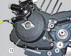
If bearing (27) has been removed, lubricate its seat with specified grease to fit it on the generator cover (13).
Fit bearing completely in its seat and orient it so that the closed side of the plastic cage is upwards.
Install the circlip (23) in the suitable seat of the generator cover above the bearing (27).
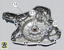
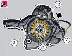
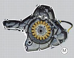
If the stator (2) has been removed, upon reassembly fit it inside the generator cover (13) so that the stator cable is faced downwards in correspondence with the cover slot.
Insert the rubber block (m) in the cover slot.
Apply the recommended threadlocker to the screws (25).
Match the stator fixing holes with the threaded ones of the generator cover, then start the screws and tighten them to a torque of 10 nm (min. 9 Nm - max. 11 Nm) (sect. 3 - 3, Engine torque settings).
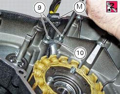
If the bracket (10) has been removed, upon reassembly check that the rubber block (m) of the cable is correctly inserted in the relevant seat on the generator cover (13).
Fit the bracket (10) on the stator cable.
Apply the recommended threadlocker to the screws (9) and start them on the cover.
Check that the stator cable is correctly positioned under the bracket and tighten the screws to a torque of 10 nm (min. 9 Nm - max. 11 Nm) (sect. 3 - 3, Engine torque settings).
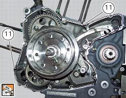
Remove any scale and grease from the mating surfaces of the left-hand crankcase half and the generator cover.
Fit the two locating bushes (11).
Spread a continuous uniform bead of ducati liquid gasket on the cover mating surface, ensuring continuity around the holes for the retaining screws and bushes.
Grease the end of the crankshaft and the gearchange shaft to facilitate installation of the cover and to prevent the sealing ring (4) from being damaged, if already installed in the cover.
While positioning the cover (13) on the crankcase half, slightly turn the timing belt drive shaft pulleys to facilitate insertion of the pump control shaft.
The notch (m) on the alternator cover must be inserted on the starter motor gear pin (p).
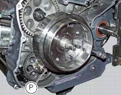
Tap the cover at different positions with a rubber mallet to facilitate its location on the shafts and locating bushes.
Note
Should it be necessary to remove the cover again, fit the puller 88713.1749 Located in the threaded holes in correspondence with the crankshaft.
Insert the fixing screws in their holes following the indications given in
the table. 
Tighten the retaining screws to a torque of 10 nm (min. 9 Nm - max. 11 Nm) (sect. 3 - 3, Engine torque settings).
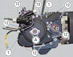
Damp the seal (4) with alcohol and install it on the generator cover (13), in correspondence with the gearchange lever.
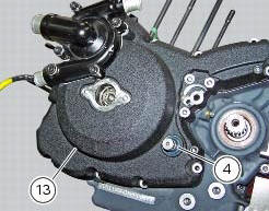
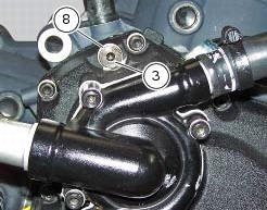
If plug (3) has been previously removed, upon reassembly insert the washer (8) on the pick-up inspection plug (3).
Apply prescribed threadlocker on the plug thread (3), start it in the generator cover (13) and tighten it to a torque of 15 Nm (min. 13 Nm - max. 17 Nm) (sect. 3 - 3, Engine torque settings).
Make
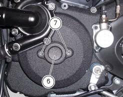
Make sure that the o-ring (5) is installed in the cover (6).
Apply threadlocker to the screws (7).
Tighten the two screws (7) that retain cover (6) with the engine crankcase to the torque of 5 nm (min. 4.5 Nm - max. 5.5 Nm) (sect. 3 - 3, Engine torque settings).
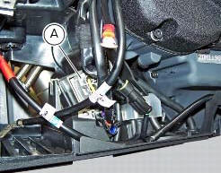
Connect the connector (a) to the generator cable.
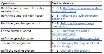
 Refitting the flywheel-alternator assembly
Fit the roller cage unit (20) with washer (18) and internal ring (19),
applying prescribed grease on the washer (18).
Install the roller cage assembly (20) with the washer (18) and inner race
...

Other materials:
How to start the engine
With the motorcycle off and the dashboard on, the on/off switch is turned to
"run off"
With the motorcycle and dashboard on, the on/off switch is turned to "run
off".
To start the engine, simply push the on/off switch up to "run on" and press the
black start button.
...
External components
Oil breather valve
O-ring
Sealing washer
Gear position sensor
Cylinder barrel/head stud
Nipple
By-pass spring
Plug
Plug
Aluminium gasket
Nut
Lock washer
Timing gear pair
Key
Key
O-ring
Screw
Locating dowel
Starter idler gear
Washer
Gear shaft
O-ring
...
Overhauling the rear swingarm
Inside the swingarm (8), in correspondence with the pivot point on the frame,
there is a pair of ball bearings (10) and a
spacer (11) on the rh side, and a pair of roller bearings (6), with sealing
rings (5), on the lh side.
To change the bearings, proceed as follows.
Remove the shims ( ...