
Ducati Diavel Service Manual: Refitting the clutch master cylinder assembly
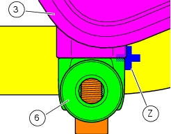
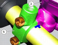
Insert the clutch master cylinder assembly (3) and the clamp (6) on the left handlebar, so that the top mating faces match the mark (z) on the handlebar as shown.
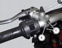
Couple terminal (6) to the clutch master cylinder control and fix them with the screws (v).
Tighten the retaining screws (v) to a torque of 10 nm +/- 10% (sect. 3 - 3, Frame torque settings) following the sequence 1-2-1 starting from the upper screw.
Locate the pipe (4) and seals (2) on the master cylinder assembly (3) and secure it with the special screw (1), without tightening it.
Warning
An incorrectly positioned hose can cause clutch faults and interfere with moving parts.
For the positioning of the clutch hose (4) and retaining clips, see the illustration at the end of this section.
Tighten the special screw (1) to the torque of 23 nm +/- 10% (sect. 3 - 3, Frame torque settings).

 Removal of the clutch master cylinder assembly
Warning
The clutch master cylinder manufacturer advises against servicing of
the clutch master cylinder (1) due to the safetycritical
nature of this component. Incorrect overhaul of this component ...
 Removal of the clutch transmission unit
Warning
The manufacturer of the clutch transmission unit (15) advises
against servicing of its internal parts due to the safetycritical
nature of this component.
Incorrect overhaul of these cri ...
Other materials:
Removing the electrical components support
Remove the following elements located inside the electrical components
support:
The battery fixing bracket (4) and the battery (14) as specified under
section 6 - 2, battery;
The voltage regulator (3) as specified under section 6 -
2,rectifier-regulator;
The solenoid starter (18) ...
Rectifier-regulator
The rectifier (1) is placed in the electrical components compartment.
The rectifier/regulator consists of an aluminium casing containing the diodes
that rectify the current produced by the
alternator. It also contains an electronic device that regulates the current
supplied by the alternator ...
Removal of the clutch-side crankcase cover
Unscrew the screws (2), (3) and (5) securing the clutch-side crankcase cover
(1).
Tap around the edge of the cover with a plastic mallet to detach it from the
crankcase half.
Remove the clutch cover (1) paying attention to the centring bushing (12).
Check the condition of the cent ...