
Ducati Diavel Service Manual: Refitting the crankshaft/connecting rod assembly
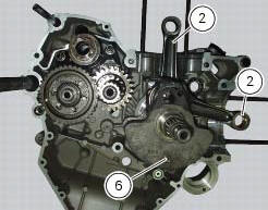
Install the connecting rod assembly (6) and (2) in the crankcase, carry out the shimming and crankcase half reassembly procedure as described in sect. 9 - 9.2, Reassembly of the crankcase halves.
Important
Make sure that the connecting rods (2) are correctly positioned in the cylinders. Incorrect positioning of the connecting rods at this stage will inevitably lead to the need to re-open the crankcase halves.
 Reassembly of the connecting rods
Before starting, check that the crankshaft main bearing journals and big-end
journals are free of burrs or evident signs of
machining: if necessary, clean the surfaces with very fine emery cloth an ...
Other materials:
Location of elements on motorcycle
(A) injection relay; (b) etv relay (throttle valve operating engine); (c)
radiator fan relay; (d) hands free relay.
(E) ecu; (g) bbs (black box system or central electronics); (f) abs hydraulic
unit with integrated control unit.
Fuses located at the rear left of the vehicle.
...
Checking the engine timing
Set the engine to the configuration described for the "checking and adjusting
the valve clearances", previously indicated.
Install tool 88765.1188 (G) in the spark plug bore to determine the piston tdc,
the gauges (h) on the tool 88765.1518
And the timing check tool (degree wheel (l) 887 ...
Reassembly of rear shock absorber - rocker arm - linkage assembly
Once the needle roller bearings (9) have been removed from the rocker arm
(18), upon reassembly fit a new needle roller
bearing (9) on drift part no. 88713.1071 And lubricate with recommended grease.
Support the rocker arm and drive the needle roller bearings into the rocker arm
bore until t ...