
Ducati Diavel Service Manual: Refitting the cylinder/piston assembly
If new units are used, it is necessary to couple the cylinders and pistons of the same selection (see paragraph "overhaul Of the cylinder barrel/piston components" of this section).
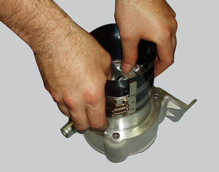
If the pistons have been separated from their cylinders, before reassembling these components, position the piston ring gaps at 120 from one another (the markings must always face the piston crown).
Note
For better sealing the piston ring gaps should be positioned at 180 intervals.
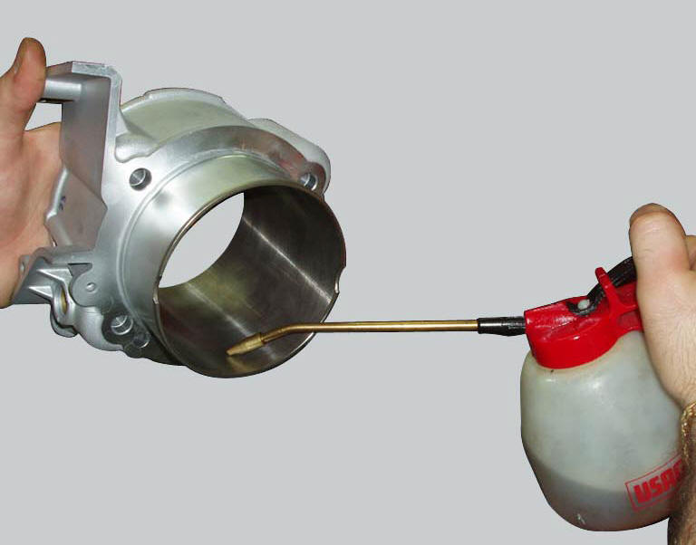
Use a universal tool to carefully insert the piston into the cylinder (first lubricate the inside of the cylinder with engine oil). Position the cylinder with the smallest valve recess is on the side of the exhaust port.
Remove
Remove any deposits and degrease the contact surfaces of the crankcase half and the cylinders.
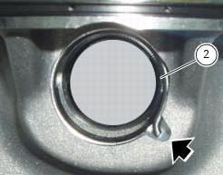
Check for the presence of the cylinders centring dowels (b) and the o-ring (c) on the base.
Apply sealant to the gasket (5) then locate the gasket on the crankcase.
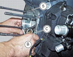
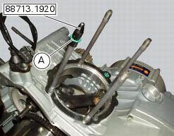
Using the cap 88713.1920, Fit the o-rings (a) on each stud bolt and guide them into their seats in the crankcase.
Bring the connecting rod small end close to tdc and slide the barrel-piston assembly (1-10) onto the crankcase studs.
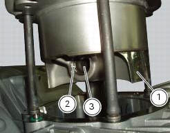
Push the connecting rod small end into the piston close to the gudgeon pin (3) bore. Lubricate and insert the gudgeon Pin.
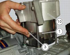
The gudgeon pin (3) must slide smoothly in the connecting rod small end bush and in the piston (1).
Close the crankcase opening with a cloth to prevent foreign objects from falling inside and then fit the retainer ring (2) as shown in the figure.
Important
Always fit new circlips (2) on reassembly.
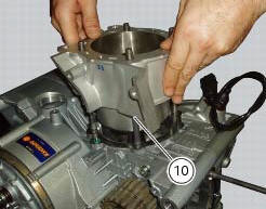
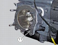
Push the cylinder barrel (10) down until it seats against the crankcase.
Refit the bushes (12).
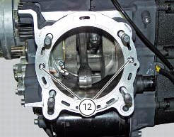
Fit the cylinder head gasket (11) over the studs. The side marked with the part number must be facing the cylinder head.
Note
The shape of the gasket prevents incorrect fitting, provided that the coolant flow holes are aligned with those on the cylinder.
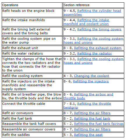
Repeat the procedure for the other cylinder and refit the cylinder heads (sect. 9 - 4.5, Refitting the cylinder head assemblies).
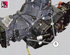
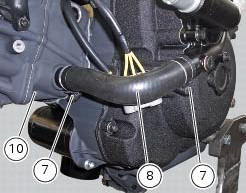
In case they have not been assembled, apply prescribed threadlocker to unions (6) and tighten them to a torque of 25 nm (min. 23 Nm - max. 27 Nm) (sect. 3 - 3, Engine torque settings).
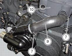
Fit the tubes (8) and (9) and tighten clamps (7) to a torque of 2.5 Nm (min. 2 Nm - max. 3 Nm) (sect. 3 - 3, Engine torque settings).
 Overhaul of the cylinder barrel/piston components
Overhauling the cylinder
Check that the walls of the cylinder bore are perfectly smooth. Measure the
cylinder bore diameter at 50 mm from the top
face and determine the size class to which it belo ...
 Clutch assembly
...
Other materials:
Refitting the front brake master cylinder
Insert the front brake master cylinder unit (1) on the right side of the
handlebar to bring the terminal internal edge in
correspondence to the bolted joints (a).
Fit the terminal (12) on the handlebar inserting the screws (15).
Tighten the terminal (12) retaining screws to a torque of 10 ...
Indicator speed avg - average speed
This function shows the average speed of the motorcycle.
The calculation is made considering the distance and time travelled since the
last trip 1 reset. When trip 1 is reset, the
value is set to zero and the first available value is shown on the display 10
seconds after the reset. Dashes "- ...
Dashboard menu option scrolling not possible
Fault codes
Dds: no fault code displayed
Dashboard: no fault code displayed
Location of connections and components
Location of left hand handlebar switchgear set connection.
Pin numbering for wiring harness side dashboard connector. ...