
Ducati Diavel Service Manual: Refitting the engine
Refitting is the reverse of removal.
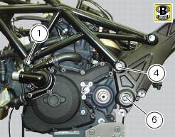
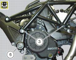
Important
Apply recommended grease and tighten the special screws (6) to a torque of 60 nm +/- 5% (sect. 3 - 3, Frame torque settings).
Tighten the nuts (3) to a torque of 48 nm +/- 5% (sect. 3 - 3, Frame torque settings).
Warning
For the assembly sequence of nuts and screws refer to sect. 7 - 17, Reassembling the frame and the lateral footrests.
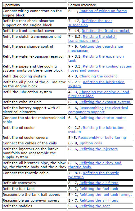
Refit the removed parts by performing the steps shown in the table and in the specific sections of the manual in reverse order.
 Removal of the engine
In order to remove engine you must first remove a series of other components
from the motorcycle.
Most of these removal procedures are described in the relative sections of this
manual.
The ...

Other materials:
Refitting the rear brake control
If the pushrod (18), clip (30) and fork (31) assembly has been dismantled,
reassemble it by screwing the nut (29) onto
the rod (18) and then screw the rod into the fork (31) to obtain the measurement
indicated in the figure.
Block the rod and tighten to a torque of 7.5 Nm +/- 10% (sect. 3 - ...
Injection and ignition
Introduction
Ignition is via a single stick coil per cylinder installed in the spark plug
well. Each thermal unit is supplied by a single
injector, placed under the throttle valve. The amount of fuel injected and the
ignition advances are determined by the
control unit specifically for each c ...
Side stand button
Introduction
The side stand button is located on the side stand. Together with the signal
from the clutch button and the neutral signal
generated by the gear sensor (transmitted to the engine control unit over the
can line), the side stand position signal is
used to enable or disable engine s ...