
Ducati Diavel Service Manual: Refitting the exhaust system
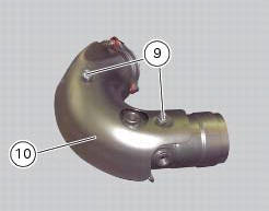
Refit the heat guard on the manifold (10) by tightening the nuts (9) to a torque of 10 nm +/- 10% (sect. 3 - 3, Frame torque settings).
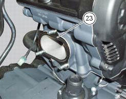
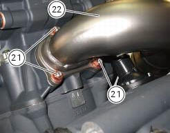
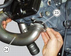
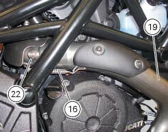
Position the vertical exhaust manifold (22) on the vertical cylinder head with the gasket (23).
Tighten the fixing nuts (21) to a torque of 10 nm +/- 10% (sect. 3 - 3, Frame torque settings).
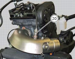
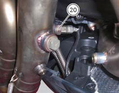
If removed, tighten the vertical lambda sensor (20) to a torque of 25 nm +/- 10% (sect. 3 - 3, Frame torque settings).
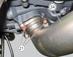
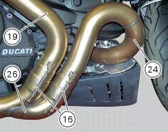
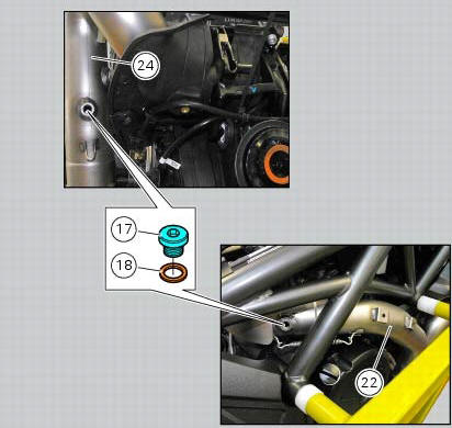
Position the horizontal exhaust manifold (24) on the horizontal cylinder head with the gasket (23).
Tighten the fixing nuts (21) to a torque of 10 nm +/- 10% (sect. 3 - 3, Frame torque settings).
If removed, tighten the horizontal lambda sensor (20) to a torque of 25 nm +/- 10% (sect. 3 - 3, Frame torque settings).
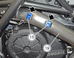
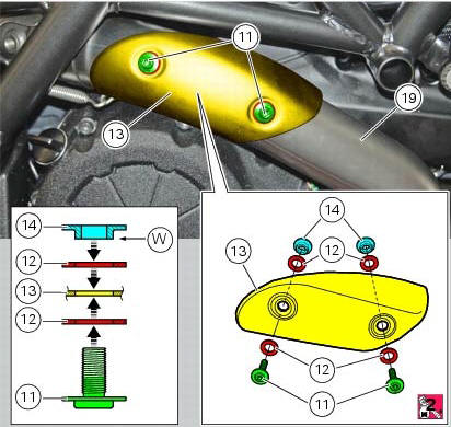
Check the presence of clips (15) on the upper exhaust pipe (19).
Fit the aramid washers (12) on the screws (11) using the recommended threadlocker.
Insert the screws (11) in the holes of the heat guard (13).
Insert the other two washers (12) and the spacers with collar (14) on the protruding ends of the screws (1).
Note
The two spacers (14) must be oriented with the collar (w) facing the heat guard (13) as shown.
Fit the heat guard (13) starting the screws (11) and tighten the screws (11) to the torque of 8 nm +/- 10% (sect. 3 - 3, Frame torque settings), making sure the washers (12) are centred to the collars (w) of the spacers (14).
Insert the upper exhaust pipe (19) into the vertical exhaust pipe (22) and block it with the spring (16).
Insert the central exhaust pipe (26) in the upper exhaust pipe (19) and the horizontal flange (24), and fix them with the springs (16).
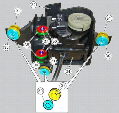
If the exhaust valve motor had been removed, fit the vibration dampers (35) into the suitable holes of the exhaust valve (34) on refitting. Fit the exhaust valve motor (34) and position it as shown on the cover (32), bringing its vibration dampers (35) fully home on the stud bolts (e).

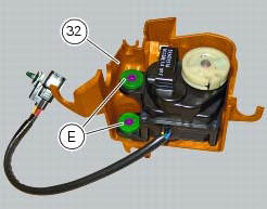
Fix the exhaust valve motor (34) to cover (32) starting the screws (37) with washers (36) in the vibration dampers (35) installed previously. Tighten the screws (37) to a torque of 3 nm +/- 10% (sect. 3 - 3, Frame torque settings).
Fit the vibration dampers (31) on the cover (32) at the positions shown.
Insert the spacers with collar (30) into the vibration dampers (31) as shown.
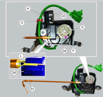
Fit the exhaust valve motor cable (m) inserting the end fitting (f) in the suitable hole of pulley (g).
Note
The exhaust valve motor cable (m) must be positioned above the wiring (h) of the exhaust valve motor (34).
Insert the cylindrical terminal (l) into the suitable seat of the exhaust valve motor (34) and make sure to bring it fully home.
Note
If it proves difficult to insert the terminal (l) fully home into its seat, apply lubricant for rubber to the terminal.
Tie the wiring (h) using a large self-locking tie wrap (n) in the area of the cover (32) shown.
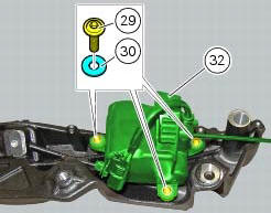
If previously removed, place the exhaust valve motor assembly (32) on the right plate of the rear subframe, start the screws (29) with washers (30) and tighten them to a torque of 10 nm +/- 10 % (sect. 3 - 3, Frame torque settings).
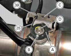
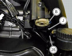
Position the control cable (25) in the plate (c).
Insert the end fitting (b) on the exhaust valve (d) and block it with the circlip (39).
Warning
Make sure the end fittings (b) at cable ends are properly fitted onto the pulleys of the exhaust valve and of its motor.
Check that the cylindrical terminal (l) is fully inserted (fully home) into the suitable seat of the exhaust valve motor.
After assembly, the cable (25) on exhaust valve and exhaust valve motor is adjusted automatically by dashboard software, that causes the valve to open fully at the first key-on, and then goes back to rest position with the valve fully closed.
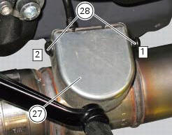
Refit the exhaust by-pass valve cover (27) by starting and tightening the screws (28) to a torque of 8 nm +/- 10% (sect. 3 - 3, Frame torque settings), starting with the front one.
Refit the silencer, as described in the paragraph "refitting the silencer" of this section.
If removed, fit the copper washers (18) to the plugs (17), start the plugs into the vertical (22) and horizontal (24) head exhaust manifolds and tighten them to the torque of 25 nm +/- 10% (sect. 3 - 3, Frame torque settings).
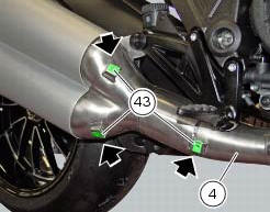
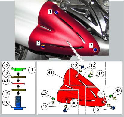
If the silencer heat guard had been removed, check the presence of clips (43) on the silencer (4).
Important
Assembly operations described below must be performed following sequence x - y - z.
Fit the washers (12) on the screws (40).
Insert the screws (40) in the holes of the heat guard (41).
Insert the other three washers (12) and the spacers with collar (42) on the protruding ends of the screws (40).
note
The spacers (42) must be oriented with the collar (j) facing the heat guard (41) as shown.
Fit the heat guard (41) by starting the screws (40).
Tighten the screws (40) to a torque of 5 nm +/- 10% (sect. 3 - 3, Frame torque settings), following sequence z - x - y and making sure the washers (12) are centred to the collars (j) of the spacers (42).
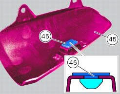
Check the presence of the rubber pad (46) on the heat guard (45).
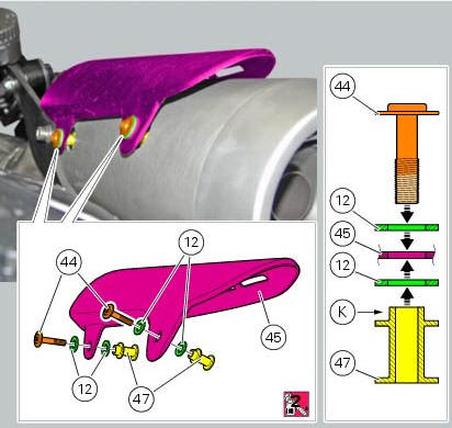
Fit the washers (12) on the screws (44) using the recommended threadlocker.
Insert the screws (44) in the holes of the rear heat guard (45).
Insert the other two washers (12) and the spacers with collar (47) on the protruding ends of the screws (44).
Note
The spacers (47) must be oriented with the collar (k) facing the heat guard (45).
Fit the heat guard (45) by starting the screws (44).
Tighten the screws (44) to a torque of 8 nm +/- 10% (sect. 3 - 3, Frame torque settings), making sure the washers (12) are centred to the collars (k) of the spacers (47).
 Removal of the exhaust system
Remove the silencer, as described in the paragraph "removing the silencer" of
this section.
Loosen the screws (28) and remove the exhaust by-pass valve cover (27).
Turn the exhaust valve pul ...
 Refitting the silencer
Position the silencer guard (41) and fix it by starting the screws (40).
Tighten the screws (40) to a torque of 8 nm +/- 10% (sect. 3 - 3, Frame torque
settings).
Insert the silencer (4) int ...
Other materials:
Stands
Side stand
Side stand switch
Screw
Plate
Screw
Inner spring
Outer spring
Nut
Rotation pivot
Screw
Screw
Screw
Nut
Clearance adjuster
Spare parts catalogue
Diavel abs stand
Diavel carbon
abs
stand
Important
Bold reference numbers in this section identify part ...
Removing the timing belt driveshaft pulleys
Use the tool code 88713.1805 To hold the driving pulley on the engine
crankcase against rotation.
Important
If this operation is carried out with the engine installed in the frame,
hold the driveshaft pulleys against rotation using the
tool code 88713.2011 Mounted on the alternator cover.
Lo ...
Turn indicators (automatic reset)
The instrument panel controls the automatic reset of the turn
indicators.
After activating one of the two turn indicators, they can be
deactivated using the reset button (12, fig. 12).
If the turn indicator is not "reset" manually, the instrument
panel will automatically switch it ...