
Ducati Diavel Service Manual: Refitting the expansion tank
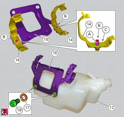
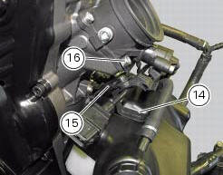
If the support (15) has been removed, place the hose clamps (14) on the bracket (15) orienting them as indicated.
Fully press the pins (a) to block the clamps (14) until pins surfaces (b) are at the same level of the clamps (14) surfaces.
Apply recommended threadlocker to the thread of the screws (18) and insert them into washers (17).
Place the bracket (15), as indicated, on the expansion reservoir (12) and tighten the screws (18) to a torque of 5 nm +/- 10% (sect. 3 - 3, Frame torque settings).
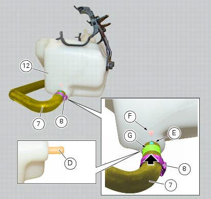
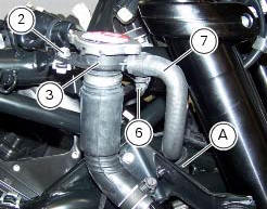
Fit the clip (8) on the hose (7).
Insert completely the hose (7) into the lower fitting (d) of the expansion reservoir (12), by orienting it so as the reference (e) of the hose matches with the arrow in relief (f) on the expansion reservoir.
Note
In case of difficulties during insertion of the hose (7) into the fitting (d) it is recommended to apply lubricant suitable for rubber to the fitting.
Orient the clamp (8) as indicated and bring it in correspondence with the area (g) of the hose (7).
Tighten the clip (7).
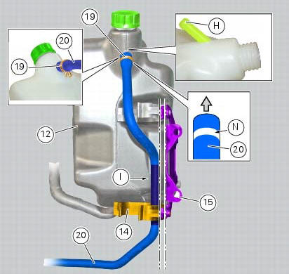
Fit the clip (19) on the hose (20).
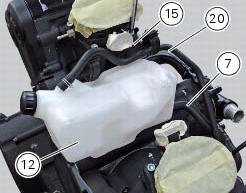
Insert completely the hose (20) on the upper fitting (h) of the expansion reservoir (5), so that the straight part (l) of the hose is parallel to the bracket (2) as highlighted by the axes (l) and (m).
Note
The hose (20) side to be inserted in the fitting (h) features the white padprinting (n).
Important
Once the assembly is completed, the hose (20) must be in contact with the internal surface of the hose clamp (1) as indicated.
Note
In case of difficulties during insertion of the hose (20) into the fitting (h) it is recommended to apply lubricant suitable for rubber to the fitting.
Block the hose (20) by means of the clip (19), by orienting it as shown.
Insert
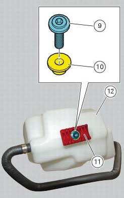
Insert the spacer with the collar (10) into the hole of the rubber mounting (11).
Fit the rubber mounting (11) as shown, by starting the screw (9).
Tighten the screw (9) to a torque of 8 nm +/- 10% (sect. 3 - 3, Frame torque settings).
Position the tank (12) with its hoses (7) and (20) and the support (15).
Position the pipes inside the clamps (14) and close them.
Tighten the screws (16) to the torque of 8 nm +/- 10% (sect. 3 - 3, Frame torque settings).
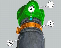
If hose (24) had been removed, insert the clip (5) on the hose (24) at the position shown.
Fit the union (3) on the hose (24) and secure it using the clamp (5).
Note
If hose (24) had been removed, insert the clip (5) on the hose (24) at the position shown.
Fit the union (3) on the hose (24) and secure it using the clamp (5).
Note
The union (3) must be oriented so that the groove on hose (24) matches the tab (a) on the hose. Orient the clamp (5) as indicated.
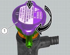
Refit the coolant circuit remote filler (4).
Position the union (3) on the frame by tightening the screw (2) to a torque of 5 nm +/- 10% (sect. 3 - 3, Frame torque settings).
Place hose (7) on the union (3) with clip (6) and tighten the latter to a torque of 1 nm +/- 10% (sect. 3 - 3, Frame torque settings).
Insert the hose (7) inside the hose guide (a).
 Removal of the expansion tank
Loosen the clamp (6), open the hose guide (a) and slide the hose (7) out of
the radiator.
Open clamps (14) and release the hoses that pass through them.
Loosen the screws (16).
Remove ...
 Removal of the cooling system hoses and unions
Loosen the clips (21) that secure the radiator/thermostat sleeve (40) and the
radiator/plug sleeve (24) to the water
radiators.
Loosen clips (25) and (43) that secure the breather pipe ...
Other materials:
Dashboard
Note
The dashboard is supplied as a single component; its internal components
cannot be renewed separately.
Important
Whenever the dashboard is renewed, the ignition key programming procedure
must be repeated.
Loosen the nuts (2) to remove the master dashboard (1) from its seat and
disconn ...
Removal of the rear brake disc
Remove the rear eccentric hub (sec. 7 - 13, Removal of the rear wheel
eccentric hub and rear wheel shaft).
Undo and remove the four fixing screws (13) of the brake disk to the wheel axle
and remove the rear brake disk (14).
Loosen the four screws (24) and remove the rear phonic wheel (25). ...
Overhauling the front wheel
Wheel bearings
Before checking the dimensions, check the wear on wheel bearings. Check for
wear by hand after cleaning and degreasing
the bearings in their seats.
Turn the inner race.
Check the amount of radial and axial play. Excessive play will cause vibration
and make the bike unstabl ...