
Ducati Diavel Service Manual: Refitting the external components
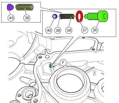
Fit the cap (39) on spring (38) until it engages.
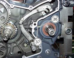
Mount ball (40), spring (38) with cap (39), washer (37) and screw (36) on the chain side half-casing by starting the screw into hole (f).
Note
The spring (38), with cap (39), must be oriented as shown.
Tighten the screw fully home to a torque of 10 nm (min. 9 Nm - max. 11 Nm).
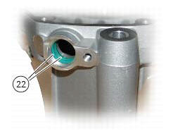
Make sure that the o-rings (22) are fitted on the crankcase.
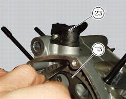
Fit the engine pickup (23) in its seat in the crankcase half.
Start the screw (25) with washer (26), and tighten it to a torque of 10 nm (min. 9 Nm - max. 11 Nm) (sect. 3 - 3, Engine torque settings).
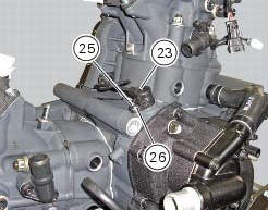
Use a feeler gauge to check the clearance between the engine sensor (23) and the timing gear (13). The value must be Between 0.6 And 0.8 Mm.
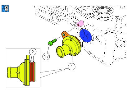
Check the condition of o-rings (2) and renew if necessary.
Install the oil vapour breather valve (1) in the crankcase along with o-rings (2), previously lubricated.
Tighten the screw (17) to a torque of 10 nm (min. 9 Nm - max. 11 Nm) (sect. 3 - 3, Engine torque settings).
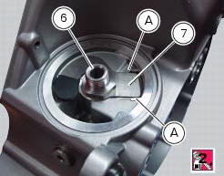
Position the by-pass spring (7) on the nipple (6) and apply the recommended threadlocker to the end of the nipple to be screwed in the crankcase half. Screw oil filter cartridge fitting (6) fully into the crankcase half, positioning the spring in the seat between the two notches (a). Tighten the nipple to a torque of 42 nm (min. 38 Nm - max. 46 Nm) (sect. 3 - 3, Engine torque settings).
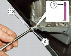
Fit the seal (9) on the oil drain plug (10). Position the seal that the side with the square edge (b) is facing the chain side crankcase half.
Clean the plug thread, apply a string of three bond tb1215 along the plug thread spreading it by the entire circumference (360).
Screw the exhaust plug (10) with relevant washer (9), and tighten it to a torque of 20 nm (min. 18 Nm - max. 22 Nm) (sect. 3 - 3, Engine torque settings).
Note
After tightening, remove any excess sealant.
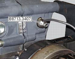
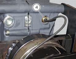
Refit idle gear position sensor (4) by means of the tool number 88713.3407.
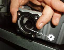
Refit the mesh filter (a) (sec. 4 - 3, Changing the engine oil and filter cartridge).
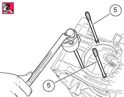
Check the condition of o-rings (16) of the stud bolts (5) and replace them if necessary.
Fit, using the tool (c), the o-rings (16) in the corresponding seats (d) of the stud bolts (5).
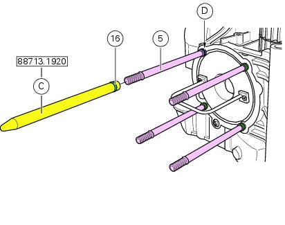
Fit the stud bolts (5) on crankcase half, by applying sealant on the thread and tightening them to a torque of 30 nm (min.
28 Nm - max. 32 Nm) (sect. 3 - 3, Engine torque settings). Use the appropriate commercial tool for this operation.
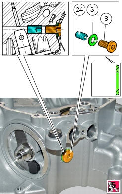
If removed, apply prescribed threadlocker on the dowel (24), tighten the latter to the torque of 15 nm (min.13.5 - Max.16.5) (Sect.3 - 3, Engine torque settings), insert the seal (3) on the service plug (8): the seal must be oriented so that the square edge faces the clutch-side crankcase half. Apply prescribed threadlocker on the plug thread (8), start it in the crankcase half and tighten it to a torque of 15 nm (min. 13 Nm - max. 17 Nm) (sect. 3 - 3, Engine torque settings).
 Removing outer components
Note
The following removal operations are required in order to renew and/or
clean the crankcase halves. If the original
crankcase halves are to be reused, then the removal of these components ...
 Removal of the timing gears
Slide out driving gear (a) of timing gear pair (13) and remove the woodruff
key (14).
Relieve the staking on the lock washer (12) of the nut (11).
Restrain the driven timing gear by ...
Other materials:
Refitting the cylinder/piston assembly
If new units are used, it is necessary to couple the cylinders and pistons of
the same selection (see paragraph "overhaul Of the cylinder
barrel/piston components" of this section).
If the pistons have been separated from their cylinders, before reassembling
these components, position the p ...
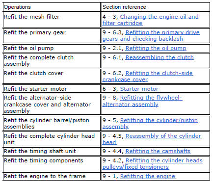
Removal of the engine
In order to remove engine you must first remove a series of other components
from the motorcycle.
Most of these removal procedures are described in the relative sections of this
manual.
The following flow chart illustrates the logical sequence in which the parts are
to be removed from th ...
Suspensions
Front
Hydraulic upside-down fork provided with external adjusters
for rebound and compression damping and preload (for inner
springs of fork legs).
Stanchion diameter:
50 mm, coated.
Rear wheel travel:
120 mm
Rear
The shock absorber is adjustable for rebound and
compression, with remot ...