
Ducati Diavel Service Manual: Refitting the front brake system
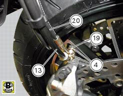
While refitting the system, pay special attention to the orientation of the pipe couplings (24) on the pump and the pipes (13) and (20) on the callipers (9) and (18).
Warning
If incorrectly positioned, the hose can affect brake operation and foul moving parts. Position the hose as shown in the figure.
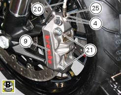
When reconnecting the brake hose to the calliper or master cylinder, make sure to install the sealing washers (4) either side of the hose end fitting.
After having oriented the pipe fitting (24) tighten the screw (3) to a torque of 23 nm +/- 10% (sect. 3 - 3, Frame torque settings).

After having oriented the pipes (13) and (20) in the front brake callipers (18) and (9) tighten the special screws (19) and (25) to a torque of 23 nm +/- 10% (sect. 3 - 3, Frame torque settings).
Note
Make sure that internal pipe fitting (13) and the external pipe fitting (20) are installed in the left brake calliper (9).
Fit the left calliper (9) over the disk.
Apply the recommended grease to the screws (21).
Hand tighten the screws (21) to secure the callipers to the fork legs.
Operate the brake lever two or three times until the circuit is pressurised and force the pads against the brake disc.
Repeat the operation for the right brake calliper (18).
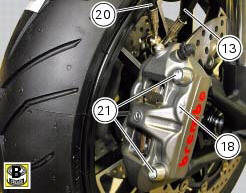
Hold the lever pulled towards the twistgrip and tighten the calliper screws (21) to the torque of 45 nm +/- 5% (sect. 3 - 3, Frame torque settings).
Insert brake rubber block (d) into grommet (b) and ensure it is centred.
Fold hose clip (b) and fasten it by starting the screw (c) in its thread.
Insert hose (13) in bracket (17) and tighten screw (16) to a torque of 8 nm +/- 10% (sect. 3 - 3, Frame torque settings).
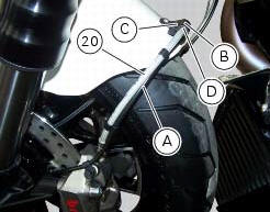

For correct position of the ties fastening the abs sensor cable (a) to front brake lines (20), please refer to sect. 7 - 6, Flexible wiring/hoses positioning.
 Refitting the brake disks
Before refitting the brake disc to the wheel, clean all contact surfaces
thoroughly and smear a medium strength
threadlocker on the threads of retaining screws (5).
Operating on the left side, f ...
 Rear brake
Rear speed sensor (abs)
Screw
Washer
Spring
Brake switch (rear)
Brake lever (rear)
Rear pump - control unit pipe
Sealing washer
Pin
Bush
O-ring
Screw
screw
Rear brake ...
Other materials:
Reassembling the frame and the lateral footrests
Apply the recommended grease to the thread of the pins (9) and of the nuts
(8).
Place the frame (1) and the brackets (2) and (3) on the engine block. Start the
pins (9) by holding the nuts (8) and insert
without tightening the screws (6) into the adjusters (4).
Position and fix the rear s ...
Removal of the exhaust system
Remove the silencer, as described in the paragraph "removing the silencer" of
this section.
Loosen the screws (28) and remove the exhaust by-pass valve cover (27).
Turn the exhaust valve pulley (a) to facilitate the throttle cable (25)
output.
Release the end fitting (b) of the cable ...
Refitting the exhaust system
Refit the heat guard on the manifold (10) by tightening the nuts (9) to a
torque of 10 nm +/- 10% (sect. 3 - 3, Frame
torque settings).
Position the vertical exhaust manifold (22) on the vertical cylinder head
with the gasket (23).
Tighten the fixing nuts (21) to a torque of 10 nm +/- 1 ...