
Ducati Diavel Service Manual: Refitting the front footrests
Note
The assembly of the front footrests is described only for the right one (2) but it is the same also for the left one.
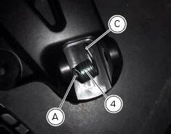
Place the spring (4) bringing the end (a) onto the footrest (2).
Place the footrest (2) in the correct position, by inserting the end (c) of the spring (4) in the hole (d) of the frame plate.
Apply the recommended grease to the pin (3).
Insert pin (3) orienting it as illustrated.
Lock the pin by inserting the circlip (5).
 Removal of the front footrests
Note
The removal of the front footrests is described only for the right one (2)
but it is the same also for the left one.
Remove the circlip (5) by releasing the pin (3).
Slide the pin (3) off ...
 Removing the front footrest brackets
Note
The assembly of the front footrests is described only for the right one
(2) but it is the same also for the left one.
Place the spring (4) bringing the end (a) onto the footrest (2).
Place ...
Other materials:
Hands free key (hf) not recognised
The activation of this (amber yellow) "warning" indicates that the hands free
system does not detect the active key (1,
fig.62) Near the vehicle.
Note
Check that the active key (a) is near the vehicle (and has not been lost)
or that it works properly.
...
Indicator cons. - Instantaneous fuel consumption
This function indicates the "instantaneous" fuel consumption.
The calculation is made considering the quantity of fuel used and the distance
travelled during the last second. The datum
is expressed in "l / 100" (litres / 100 km); it is possible to change the units
of measurement for "consump ...
Alternator
It is equipped with a 12 v, 430 w generator, consisting of a fixed element
(stator, a) located on the generator cover and
of a movable element (rotor, b) fixed to the crankshaft.
Note
To check the battery charging system for faults, use the dds diagnosis
instrument and follow the instruct ...