
Ducati Diavel Service Manual: Refitting the front sprocket
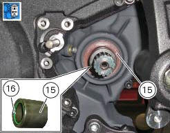
Grease the o-ring (16) and install it on the front sprocket spacer (15).
Fit the spacer, from the o-ring side, on the secondary shaft and drive it fully home against the inner ring of the bearing.
Check that the splines of the gearbox secondary shaft and the sprocket are in perfect condition.
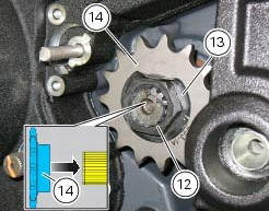
Fit the engine pinion (14) on the gearbox secondary shaft by orienting it as indicated. Install the safety washer (13).
Tighten the nut (12) to the torque of 186 nm +/- 5% (sect. 3 - 3, Frame torque settings).
Bend the washer (13).
Fit the chain and close it using the tool with code 88713.1344 That was used to open the chain.
The tool is composed of a holder (a), punch (b), body (c) and two wrenches (d) and (e) and link plate holder (f).
Connect the two halves of the chain with the external link and manually fit the plate onto the pins.
Warning
Lubricate the pins abundantly; try to avoid touching them with your hands.
Fit the holder (a) onto the external link.
Fit the punch (b) into the body (c) and the plate holder (f).
Fit the body (c) onto the holder (a) which holds the chain in position.
Manually turn the bolt (g) until the plate holder (f) is seated against the plate itself.
Use wrenches (d) and (e) to turn the bolt (g) clockwise until the chain pin is in contact with the holder (f).
Remove the holder (a) from the tool.
Manually turn the bolt (g) until the punch (b) locates against the pin, taking care that they are aligned with each other.
Use wrenches (d) and (e) to turn the bolt clockwise until the punch (b) is seated against the chain plate.
To complete reassembly, repeat the entire procedure with the second pin.
Warning
Carefully check the two pins: the figure shows the correct result of the procedure.
Adjust the chain tension (sect. 4 - 3, Adjusting the chain tension).
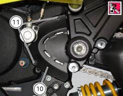
Apply the recommended threadlocker to the screws (11).
Fit the sprocket cover (10) tightening the screws (11) to the torque of 6 nm+/- 10% (sect. 3 - 3, Frame torque settings).
 Removing of the front sprocket
Undo the screws (11) and remove the chain cover (10).
Loosen the chain (sect. 4 - 3, Adjusting the chain tension).
Remove the chain with the tool code 88713.1344.
The tool is composed of a ...
 Replacing of the rear sprocket
Lock the wheel axle rotation.
Remove the clip (1).
Loosen the locking nut (2) with a socket wrench.
Fully unscrew the nut (2) and remove the washer (3) and the flange (5) with the
sproc ...
Other materials:
Reassembly of the oil pump
Check that the circlip (3) and tongue (13) are present on the pump.
Fit the pump drive gear (12) on to the oil pump and secure it by installing the
circlip (6) in its groove.
Insert the by-pass valve pump (17), the spring (16) and screw the plug (14).
Tighten the plug (14) to a torque of ...
Evaporative emissions canister system (usa versions only)
Usa models are equipped with an additional system with an evaporative
emissions canister that prevents fuel fumes from
being discharged into the atmosphere.
The breather hose (4) is connected to the canister filter (1); when the fuel
has been filtered, it is returned through the
hose (2) to t ...
Removal of the camshafts
Unscrew and remove the screws (7) and the o-rings (8) from the cylinder head
covers.
Remove the cylinder head cover (6).
Remove the gaskets (4) and (9).
Repeat the same procedure for the other cylinder head cover. Unscrew the
screws (3) securing the camshaft supports.
Withdra ...