
Ducati Diavel Service Manual: Refitting the fuel tank fairings
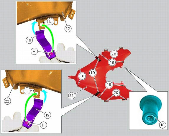
Make sure that the following components are fitted on the tank fairing (22):
- Spacers (18);
- Seals (20).
Fit the clips (19) to the central cover (22) at the positions shown, inserting the tabs (h) into the slots (l).
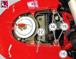
Apply threadlocker to the screws (14).
Place the tank fairing (22) on the tank and keep it in position by starting the screws (14) together with the relevant nylon washers (15).
Tighten to torque of 2 nm +/-10% (sect. 3 - 3, Frame torque settings) the screws (14).
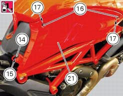
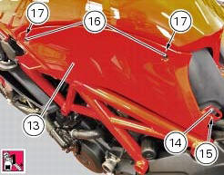
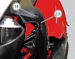
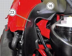
Fit the tank lh fairing (21) and keep it in position by starting the screws (16) together with the relevant washers (17).
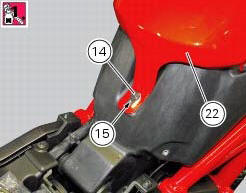
Apply some threadlocker on the screw (14), fit the nylon washer (15) and start the screw.
Tighten the screw (14) to a torque of 2 nm +/- 10% (sect. 3 - 3, Frame torque settings) and the screws (16) to a torque of 0.33 Nm +/-10% (sect. 3 - 3, Frame torque settings).
Fit the tank rh fairing (13) and keep it in position by starting the screws (16) together with the relevant washers (17).
Apply some threadlocker on the screw (14), fit the nylon washer (15) and start the screw.
Tighten the screw (14) to a torque of 2 nm +/- 10% (sect. 3 - 3, Frame torque settings) and the screws (16) to a torque of 0.33 Nm +/-10% (sect. 3 - 3, Frame torque settings).
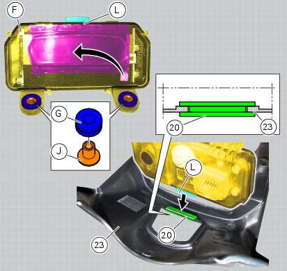
Fit the vibration dampers (g) to the master dashboard (f).
Insert the spacers with collar (j) onto the vibration dampers (g).
Fit the vibration damper (20) to the tank plug cover (23) at the position shown.
Important
On refitting, make sure that the vibration damper (20) is fully in place.
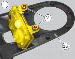
Fit the master dashboard (f) on the tank plug cover (23) inserting tab (l) into the vibration damper (20).
Fix the master dashboard (f) to the cover (23) by tightening the screws (m) to a torque of 2 nm +/- 10% (sect. 3 - 3, Frame torque settings).
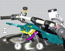
Place the tank plug cover (23) on the vehicle and connect connector (e) to the dashboard (f); push connector until an audible click indicates proper engagement.
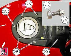
Apply threadlocker to the screws (25).
Fit the tank plug cover (23), fit spacers (24), and start screws (25) and screws (16).
Tighten the screws (25) to a torque of 2 nm +/- 10% (sect. 3 - 3, Frame torque settings) and the screws (16) to a torque of 0.33 Nm +/-10% (sect. 3 - 3, Frame torque settings).
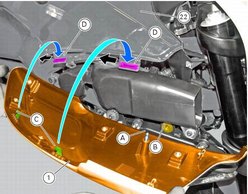
Lubricate the seals (d) of the central tank cover (22) using lubricant specific for rubber.
Position the front rh half-fairing (1) by inserting the tabs (c) into the seals (d) pushing downwards (blue arrows); after that, slide the half-fairing completely to the rear side of the motorcycle (red arrows).
Block the front rh half-fairing (1) by forcing pin (a) into the receptacle (b) in the rh water radiator.
Warning
Before pushing on the pin (a), make sure it is centred in the receptacle hole (b). Then - and not until after checking for proper position - push moderately and increasingly harder until you hear the component engage.
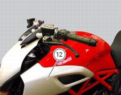
Before tightening the screws securing the front left half-fairing (12) and the front right half-fairing (1), proceed as follows: visually check the distance between the front left half-fairing (12) and the central tank cover (22) along the upper mating edges of both parts.
Visually check the distance between the front right half-fairing (1) and the central tank cover (22) along the upper mating edges of both parts.
If the parts do not mate equally, shift the front half-fairings (12) and (1) forward or backward as required until achieving a condition in which the half-fairings (12) and (1) are at the same distance from the central tank cover (22).
After tightening, check again to ensure that the front half-fairings (12) and (1) are at the same distance from the tank cover (22). If not so, repeat the above procedure.
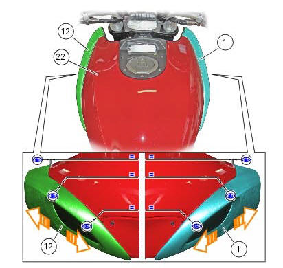
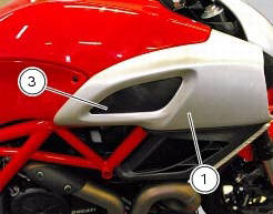
Fix the front rh half-fairing (1) by tightening the screw (3) to a torque of 0.33 Nm +/- 10% (sect. 3 - 3, Frame torque settings).
Follow the same procedure to reassemble the lh half-fairing (12).
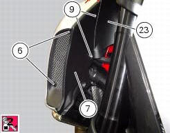
Apply threadlocker to the screws (9).
Fit the rh air inlet (7) and fix it to the tank plug cover (23) by starting the screws (6) and (9).
Tighten the screws (9) to a torque of 2 nm +/- 10% (sect. 3 - 3, Frame torque settings) and the screws (6) to a torque of 1.5 Nm +/-10% (sect. 3 - 3, Frame torque settings).
The procedure is the same for the lh air inlet (8).
 Reassembly of the front half-fairings
Fit the clips (2) on the front rh half-fairing (1).
Join the rh support (4) and the front rh half-fairing (1) and keep them in
position by starting the screws (5).
Note
To mount the rh suppor ...
 Seat
Seat
Seat
Seat cover
Rubber mounting
Special screw
Plate
Latch
Spare parts catalogue
Diavel abs seat
Diavel carbon
abs
seat
Important
Bold reference numbers in this section identi ...
Other materials:
Replacing the rear phonic wheel sensor
Disconnect the rear abs sensor (5) connector (c) from the main electric
wiring.
Open all the retainer clamps of the rear abs sensor cable (5): refer to table of
sect. 7 - 6, Flexible wiring/hoses
positioning.
Remove the rear abs sensor (5) from its seat on the rear calliper mounting ...
Refitting the rear mudguard
Place the rear mudguard (8) on the swingarm, fitting the screws (9) with
recommended threadlocker.
The screw (9) in the bottom hole of the rear mudguard (8) must be installed with
the washer (r).
Tighten the screws (9) to a torque of 5 nm +/- 10% (sect. 3 - 3, Frame torque
settings).
...
Hydraulic clutch control
Special screw
Sealing washer
Clutch master cylinder
Clutch hydraulic pipe (metal braid)
Screw
Spare stand
Washer
Microswitch
Pin
Bleed valve
Screw
Roller
O-ring
Clutch control rod
Clutch lever
Dust cap
Bleed valve
Special screw
Sealing washer
Boot
Plug
...