
Ducati Diavel Service Manual: Refitting the gear interlock plunger and pawl assembly
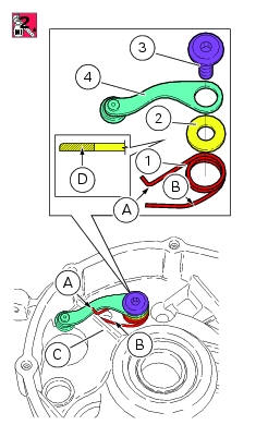
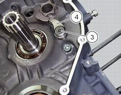
On the special screw (3), fit the gear pawl lever (4), orienting it as shown in the figure, the washer (2) with the square edge side (d) facing the clutch-side crankcase half, and the spring (1), positioning it so that the hook end (a) is facing the gear pawl lever. Locate the hook end (a) of the spring on the gear pawl lever as shown in the figure.
Apply threadlocker to the screw thread. Start the screw in the crankcase half. Position end (b) of the spring so that it rests against rib (c) of the crankcase half, as shown in the figure. Tighten the screw (3) to a torque of 18 nm (min. 16 Nm - max. 20 Nm) (sect. 3 - 3, Engine torque settings). Manually move the gear stopper to check for proper spring operation.

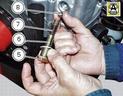
Grease and then fit the ball (8), spring (7), and seal (6) to the gear interlock plunger (5).
Lock the plunger (5) to a torque of 30 nm (min. 27 Nm - max. 33 Nm) (sect. 3 - 3, Engine torque settings).

 Disassembly of gear interlock plunger and pawl assembly
Unscrew the interlock plunger screw (5) and remove the seal (6), spring (7)
and the detent ball (8).
Unscrew the clutch-side crankcase half screw (3) and remove the pawl (4),
washer (2) a ...
 Refitting the gear selector lever
Position the gearbox drum selector fork in the centre of the gear rollers.
Position the gear selector lever (21) together with control shaft, spring and
plate into the chain-side crankcase half.
...
Other materials:
Riding style function (riding style change)
This function changes the motorcycle riding style.
Each riding style is associated with a different intervention level of the
traction control (dtc - ducati traction control) and
different engine power and output.
To change the motorcycle riding mode, press the reset button once
(3) and th ...
Refitting the expansion tank
If the support (15) has been removed, place the hose clamps (14) on the
bracket (15) orienting them as indicated.
Fully press the pins (a) to block the clamps (14) until pins surfaces (b) are at
the same level of the clamps (14) surfaces.
Apply recommended threadlocker to the thread of the ...
Stored lap display function
This function displays the stored laps.
To access the function it is necessary to view the "setting" menu page 48, using
button (1, fig. 14) ?"" or (2, fig.
14) ?" " select the "lap" function and
press the reset button
(12, fig. 12) To go to next pag ...