
Ducati Diavel Service Manual: Refitting the gear selector lever
Position the gearbox drum selector fork in the centre of the gear rollers.
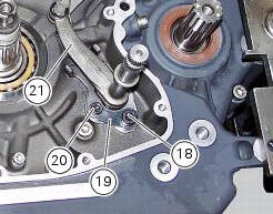
Position the gear selector lever (21) together with control shaft, spring and plate into the chain-side crankcase half.
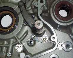
Insert the screws (18) and (20) with the spacer (19).
Temporarily fit gear change lever (or a service lever) and engine pinion and shift to neutral gear.
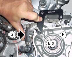
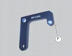
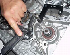
Place the tool 88713.3334 On the gear claw.
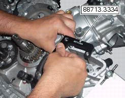
Place the tool 88713.3334 Inserting the clutch rod (e) into the tool hole, block the pin (f) of the tool in the gear claw pressing with the hand in the point (g) (claw stroke lock plate) towards the right, as shown in photo.
Tighten the screw (18) in this position to a torque of 36 nm (min. 34 Nm - max. 38 Nm) and screw (20) to a torque of 16 nm (min. 15 Nm - max. 17 Nm) (sect. 3 - 3, Engine torque settings).
Warning
Make sure that the gear selector lever fixing screws (18) and (20) are those indicated in our spare parts catalogue. They Must be screws of class 12.9 In order to respect the tightening torque indicated above (sect. 3 - 3, Engine torque settings).
Start tightening the first screw (18), and continue with screw (20).

Remove service tool no.
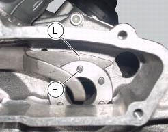
Check that the pin (h) placed on the gear drum is axially to the notch (l) on the gear claw (with gear in neutral).
With the gearbox in neutral, check that the lever travel is the same when shifting up and down. The same should apply when a gear is engaged.
Operate the gearchange lever and turn the front sprocket at the same time to check that all the gears engage when shifting up and down.
Remove the previously installed lever and sprocket.

 Refitting the gear interlock plunger and pawl assembly
On the special screw (3), fit the gear pawl lever (4), orienting it as shown
in the figure, the washer (2) with the square
edge side (d) facing the clutch-side crankcase half, and the spring (1),
...
 Gearbox shafts
Shim, thickness 1
Gearbox primary shaft
Shim, thickness 0.5
Needle roller bearing
5Th speed driving gear
Splined washer, thickness 0.5
Circlip
3Rd- 4th speed driving gear
6Th sp ...
Other materials:
Symbols
Ducati motor holding s.P.A. Advises you to read this manual
carefully in order to become familiar with your motorcycle. If
in doubt, please contact a ducati dealer or authorised
service centre. The information contained herein will prove
useful on your trips - and ducati motor holding s.P.A. Wis ...
Check the idle and the co amount with warm engine
Start the engine;
Switch on the dds and check that it does not signal any error (otherwise
consult the relevant paragraph of this manual
to reset the error and proceed with the idle check);
Enter the "self diagnosis" menu by selecting the diavel model in the
available vehicle version. ...
Lcd unit functions
Speedometer.
Gives road speed.
Rev counter.
Indicates engine revs per minute.
Clock.
Water temperature indicator.
Indicates engine coolant temperature.
Important
Stop riding if the temperature reaches the maximum
value, otherwise the engine might be damaged.
...