
Ducati Diavel Service Manual: Refitting the gearchange mechanism
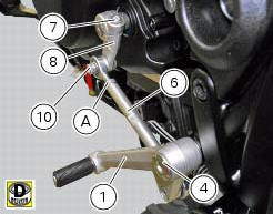
Make sure that the gearchange linkage assembly (6) is installed with the ball joint with a left-hand thread (a) facing the lever (8).
Apply the recommended grease to the non-threaded surface of the pin (4).
Fit the first o-ring (5) in the pin (4).
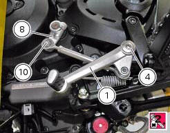
Start the pin (4) in the gearchange lever (1). Smear recommended grease on the second o-ring (5). Insert the second o Ring (5) and the washer (9).
Apply the recommended threadlocker to the threaded side of the pin (4). Fit the gearchange lever (1) on the footrest bracket and tighten the pin (4) to a torque of 23 nm +/- 10% (sect. 3 - 3, Frame torque settings).
Fit the lever (8) on the gearchange control assembly, and start the screw (10).
Tighten the screw (10) to the torque of 10 nm +/- 10% (sect. 3 - 3, Frame torque settings).
Fit the gear control unit inserting the lever (8) on the gear control pin, apply threadlocker on the screw (7) and insert it on the lever (8).
Tighten the screw (7) to a torque of 10 nm +/- 10% (sect. 3 - 3, Frame torque settings).
 Disassembly of the gearchange mechanism
Refer to the exploded view at the beginning of this section for indications
on disassembly and renewal of gearchange
components.
If the bushing (2) inside the pedal (1) needs replacing, grease t ...
 Fork
Fork
...
Other materials:
Indicator trip time - trip time
This function shows the vehicle trip time.
The calculation is made considering the time travelled since
the last trip 1 reset. When trip 1 is reset, the value is set to
zero.
The active phase calculation occurs when the engine is
running and the vehicle is stopped (when the vehicle is not
...
Dds diagnosis instrument
The main functions of the dds diagnosis instrument can be summarised as
follows:
Retrieval of errors (faults) of the ignition-injection system stored in
the engine control unit memory and their subsequent
deletion, if required.
Reading of engine parameters (rpm, coolant and air temperat ...
Removal of the rear wheel eccentric hub and rear wheel shaft
Before removing the eccentric hub, you must first remove the parts listed
below.
Slacken off the screws (34).
Remove the spacer (20) and the inner ring (21) on the chain side and remove the
wheel shaft (31) with the brake disc
(30) from the opposite side.
Remove the circlip (19 ...