
Ducati Diavel Service Manual: Refitting the handlebar
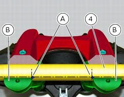
Position the handlebar (4) so that the external lower corner of the marks (a) on the handlebar matches the upper internal corner of the lower u-bolts (b) as shown.
Apply the recommended grease to the threads and undersides of the heads of the screws (3).
Important
Position the upper u-bolt (1) as shown.
Refit the upper clamp (1) and insert the screws (3).
Tighten the screws (3) to a torque of 25 nm +/-5% (sect. 3 - 3, Frame torque settings), applying the sequence 1-2-3-4-3, as indicated in the figure.
Adjusting the throttle cable
To operate on the set screws of the throttle grip cables, consult sect. 4 - 3, Adjusting the throttle cable.
 Removal of the handlebar
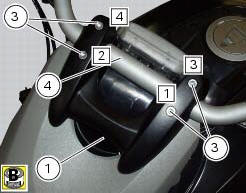
Unscrew and remove the screws (3) securing the upper clamp (1).
Remove the upper clamp (1).
Remove the handlebar (4) from its seat on the steering head.
To remove the grips (5), refer ...
 Removal of the throttle twistgrip
Peel back the rubber sleeve (a) protecting the throttle control cables.
Undo the screws (b) of the throttle grip (6) and open the command.
Disconnect the throttle grip cables (10) by unhooking ...
Other materials:
Refitting the timing belt driveshaft pulleys
To fit the circlip (10) in the driveshaft seat, use the tool code 88713.2834.
Install the inner spacer (17) on the driveshaft, taking care to align the
notch in the spacer with the slot for the woodruff
key.
Fit the first woodruff key (16) on the timing belt driveshaft.
Locate the ...
Overhaul of the crankcase halves
Carefully examine the engine crankcase halves.
Check that the surfaces of the crankcase halves are perfectly flat using a
reference surface.
Check that the bearings (1) and (18), and the bushings (2) and (17) are in
optimum conditions. Note that the main
bearings must always be changed in p ...
Removing the frame and the lateral footrests
Loosen the two special screws (6) to separate the frame (1) from the lateral
brackets (2) and (3).
On the left side of the vehicle block retaining pins (9) and loosen the nuts (8)
on the right side at the same time.
Slide out the retaining pins (9) and remove the frame (1) from the lateral ...