
Ducati Diavel Service Manual: Refitting the lubrication system
Note
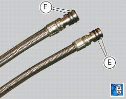
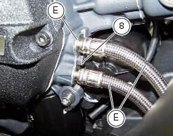
Before fitting the pipes (7), it is recommended to check the presence of the o-rings (e). Lubricate them by using engine oil.
If the nipples (5) have been removed from the radiator insert a washer (6) on each nipple (5) and apply specific threadlocker on threads on the radiator side.
note
The washers (6) must be inserted on the side of the nipples (5) which represent the thread with the smaller diameter, and must be oriented with the cutting edge to the radiator.
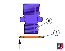
Start the nipples (5) on the oil cooler (1) and tighten them to a torque of 23 nm +/- 10% (sect. 3 - 3, Frame torque settings).
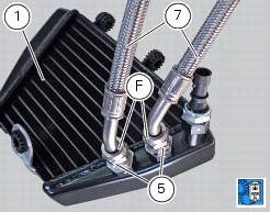
Lubricate the nipples threads (5) with engine oil.
Attach the hoses to the nipples (5), finger-tightening the ring nuts (f) of the hoses on the nipples.
Tighten the ring nuts (f) to a torque of 18 nm +/- 5% (sect. 3 - 3, Frame torque settings).
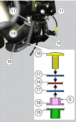
If the horizontal exhaust heat guard assembly was removed, on refitting insert the screw (16) with a washer (17) in heat guard (14) to join it to the exhaust protection (15), and then fit the other washer (17) with spacer (18) on the protruding end of the screw.
Note
The spacer (18) must be oriented with the collar (g) facing the heat guard (14).
Fit the heat guard (14) on the exhaust protection (15) by tightening the screw (16) to a torque of 3 nm +/- 10% (sect. 3 - 3, Frame torque settings).
Fit the heat guard (14) and heat protection (15) assembly on the horizontal cylinder head with support (10) by tightening the screw (11) to a torque of 10 nm +/- 10% (sect. 3 - 3, Frame torque settings).
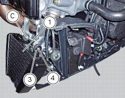
Check that the vibration damper mounts are present on the oil cooler (2).
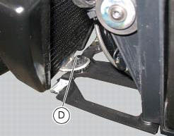
Fit the oil cooler (1) by inserting it first into pins (c) and (d) of the supporting bracket.
If you encounter any difficulties, apply lubricant for rubber to the pin (d).
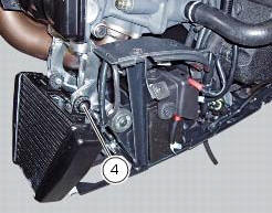
Insert the spacer (3), the screw (4) and start the screw (4).
Position the pipes (7) in the crankcase half. Position the plate (9).
Tighten the screw (8) to the torque of 10 nm +/- 10% (sect. 3 - 3, Frame torque settings).
Tighten the screw (4) to the torque of 6 nm +/- 10% (sect. 3 - 3, Frame torque settings).
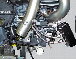
Close the pipe grommet (11).
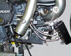
If previously removed, place the sensor (12) with washer (13) on cooler and tighten it to a torque of 19 nm +/- 10% (sect. 3 - 3, Frame torque settings).
Connect the sensor (12) to the main wiring.
 Removal of the lubrication system
Disconnect the sensor (12) of the main wiring.
Open the pipe grommet (11).
Undo the screw (8) and slide out the plate (9).
Slide the tubes (7) out of the half-casing having care not to ...
 Cooling system
...
Other materials:
Active key
Introduction
The active key (1) communicates with the hands free system by radio. In order
to function, the key must be within a 1.5
Metre radius from the antenna (located in the document compartment under the
seat).
In the event of a flat key battery or of an internal transmitter circuit f ...
Refitting the shock absorber support
If you had removed them, apply recommended grease on the threads of the
adjusters (4) and the ring nuts (3) having
care not to have grease on the surface (c) of the adjusters.
Tighten the adjusters on the ring nut side opposite to that featuring flats
until bringing the surfaces as close as ...
Alternator
It is equipped with a 12 v, 430 w generator, consisting of a fixed element
(stator, a) located on the generator cover and
of a movable element (rotor, b) fixed to the crankshaft.
Note
To check the battery charging system for faults, use the dds diagnosis
instrument and follow the instruct ...