
Ducati Diavel Service Manual: Refitting the number plate holder
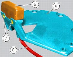
Place the number plate light (5), as indicated, on the number plate holder plate (8) and tighten the screws (7) to a torque of 2 nm +/- 10% (sect. 3 - 3, Frame torque settings).
Thread the number plate light wiring (c) into the opening in the number plate holder plate as shown.
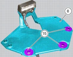
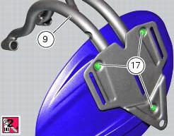
Fit the vibration dampers (15) in the corresponding holes of the number plate holder plate (8). Position the splashguard (16) on the number plate support subframe (9).
Apply prescribed threadlocker on the screw threads (17).
Fix the splashguard (16) by tightening the screws (17) to a torque of 5 nm +/- 10% (sect. 3 - 3, Frame torque settings).
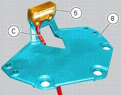
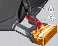
Position the number plate light wiring (c) into the seat in the number plate holder plate (8) as shown.
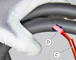
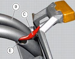
Insert the connector (d) of the number plate light wiring (c) into the hole (e) in the number plate support subframe (9), threading it out of the hole on the opposite side.
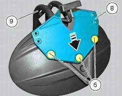
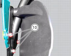
Fit the number plate holder plate (8) to the number plate support subframe (9), fitting the special screws (6) into the vibration dampers and starting the nuts (10) on the opposite side.
Note
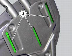
Slide the plate (8) along the slots (g) in the subframe (9) until bringing it all the way towards the bottom side.
Tighten the special screws (6) to a torque of 5 nm +/- 10% (sect. 3 - 3, Frame torque settings), by holding the nuts (10) on the opposite side.
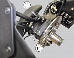
Reposition the assembly on the swingarm and tighten the screws (11) to a torque of 25 nm +/- 10% (sect. 3 - 3, Frame torque settings).
 Removal of the licence plate holder
Disconnect connector (5) of the number plate holder wiring from the main one.
Release the number plate holder light cable from the ties and the cable grommets
as indicated in sect- 7 - 6, fle ...
 Removal of the tail light
Disconnect the connectors (a) and (b) of the tail lights (1) and (13).
Loosen the screws (4) and slide the tail lights (1) and (13) to the rear side;
recover the four spacers (3) and the wash ...
Other materials:
Disassembly of gear interlock plunger and pawl assembly
Unscrew the interlock plunger screw (5) and remove the seal (6), spring (7)
and the detent ball (8).
Unscrew the clutch-side crankcase half screw (3) and remove the pawl (4),
washer (2) and spring (1).
...
Refitting the seat
Note
Apply recommended grease to the hole (a) of latch (6).
Fit the seat (1) as follows: insert the tabs (b) (on the front side) under
the rubber pads (c) of the gloves compartment;
then push the seat rear side until hearing the lock latch click.
...
Removal of belly fairing
Loosen and remove the screws (5) and (8) that secure the oil cooler (7) to
the rh (1) and lh (2) belly fairings.
Remove the lh belly fairing (2) by loosening the screws (3) with relevant
washers (4) and the screws (12).
Follow the same procedure to remove the rh belly fairi ...